PSoC5LP Lab 16: Rotary Encoder Module
Objective
- Learn how to connect the Keyes KY-040 rotary encoder to PSoC5LP.
- Detect the direction of rotation.
- Count the steps (pulses) to determine position.
Overview
Rotary Encoder
Rotary Encoder
Rotary encoders are sensors used in embedded systems to measure a rotating shaft's rotation, position, or angular movement. They convert a shaft's angular position or motion into digital or analog output signals, which microcontrollers or embedded systems can process. Rotary encoders are widely used in applications where precise control of position, direction, or speed is essential, such as robotics, motor control, industrial automation, and consumer electronics.
There are two main types of rotary encoders: incremental and absolute.
- Incremental Encoders: These generate pulses as the shaft rotates, allowing the system to detect the relative position and speed. However, they don't track the exact position and need a reference point for full positional awareness.
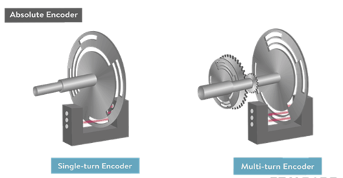
- Absolute Encoders: These encoders provide a unique position value for each rotation angle, enabling accurate position tracking without needing a reference point.
Most rotary encoders consist of an optical or magnetic disc attached to a shaft and a sensor that detects changes in the disc pattern as the shaft rotates. The output from a rotary encoder is often a series of pulses, which embedded systems use to determine speed, direction, and position by counting and interpreting these signals.
Incremental Encoders
Incremental Encoders
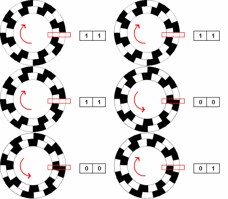
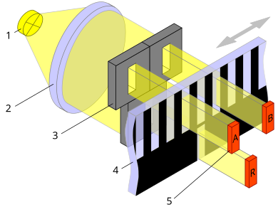
An incremental encoder is a rotary encoder that generates a series of pulses as the shaft rotates. It does not give an absolute position but provides information about the movement direction and speed by counting pulses. Incremental encoders are widely used in applications like motor control, where relative positioning or speed is essential.
Key Components of an Incremental Encoder
- Disk: A rotating disk with alternating transparent and opaque sectors.
- LED or Light Source: Illuminates the disk.
- Photodetector: Detects light patterns through the disk and generates pulses.
- Metal Ring with Contact Points: In some designs, a metal ring with tabs or protrusions makes contact with internal conductive segments to produce pulses mechanically.
Working Principle
As the shaft rotates, the photodetector senses light through the disk's alternating sectors, or in mechanical designs, the metal ring’s tabs make and break contact with the internal contact points. This pattern is converted into a square wave, creating pulses representing shaft movement.
- Channels (A and B): Incremental encoders often have two output channels, A and B. These channels produce square waves with a 90° phase difference (quadrature output). This phase shift allows the determination of both speed and direction of rotation.
- Index Pulse (Z): Some encoders include an index pulse (Z channel) that generates a single pulse per revolution, serving as a reference position.
Determining Direction
By reading both Channel A and Channel B, the direction of rotation can be determined:
- Clockwise (CW): Channel A leads Channel B.
- Counter-Clockwise (CCW): Channel B leads Channel A.
How to Detect the Rotation Speed of an Incremental Encoder
Detecting the rotation speed of an incremental encoder involves measuring the frequency or time between pulses generated by the encoder’s output channels (Channel A and/or Channel B). Here are common methods used to calculate rotation speed:
- Pulse Counting with a Fixed Time Interval
- In this method, the system counts the number of pulses the encoder generates within a fixed time interval.
- For example, suppose the encoder produces 100 pulses in one second, and each pulse represents a fixed angular movement. In that case, the speed can be calculated by multiplying the number of pulses by the angular movement per pulse.
- This method works well for steady speeds but may not capture rapid speed changes accurately.
Formula: $Speed\, (in\, degrees/\sec ) = {{Number\, of\, Pulses \times Degree\, per\, Pulse} \over {Time\, Interval}}$ - Time Measurement between Pulses
- Another approach is to measure the time interval (in microseconds or milliseconds) between consecutive pulses on a single channel (e.g., Channel A).
- This interval can be inversely proportional to the speed. The shorter the interval between pulses, the higher the speed.
- This method is especially useful for detecting changes in speed in real time.
Formula: $Speed\, (in\, RPM) = {{60 \times Pulse\, per\, Revolution} \over {Time\, between\, Pulse}}$ - Using Quadrature Signals for Higher Precision
- Since incremental encoders generate two channels (A and B) with a 90° phase difference, they can provide higher resolution when both channels are read. Each transition (rising and falling edges) can be treated as an individual pulse.
- By counting all transitions in both channels, you effectively quadruple the pulse count per revolution, which allows for more precise speed calculations.
Absolute Encoders
Absolute Encoders

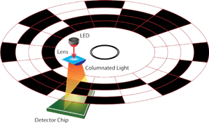
An absolute encoder provides a unique code or output for each position, allowing it to track the exact angular position of the shaft at any given moment. Unlike incremental encoders, absolute encoders retain the position information even when powered off, making them ideal for applications that require precise positioning, such as robotics, CNC machines, and industrial automation.
Types of Absolute Encoders
- Single-Turn Absolute Encoder:
- Provides unique position information within a single 360° rotation.
- Each position within one rotation has a unique digital code.
- Resets to the initial position after one complete turn.
- It is ideal for applications requiring precise positioning within a single turn, such as servo motors and rotary controls.
- Does not track multiple turns or rotations.
- Multi-Turn Absolute Encoder:
- Records the angle within a single rotation and the number of complete rotations.
- Can uniquely identify positions across multiple revolutions.
- Retains position data even after several turns, allowing for precise multi-turn tracking.
- Suitable for applications requiring accurate positioning over multiple turns, such as in elevators, robotics, and industrial automation.
- Maintains position information even if power is lost, ensuring reliability for critical applications.
KY-040 Rotary Encoder
Keyes KY-040 Rotary Encoder
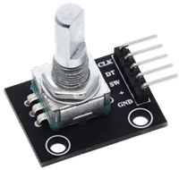
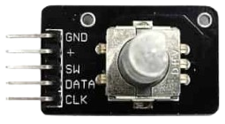
The Keyes KY-040 is a commonly used incremental rotary encoder module in embedded systems. It provides precise control over rotational input, making it ideal for volume adjustments, menu navigation, and motor control applications.
Key Features:
- Type: Incremental Rotary Encoder
- Rotation: The KY-040 allows unlimited 360° continuous rotation without mechanical stops.
- Steps per Revolution (Detents): It has 20 steps (detents) per full 360° rotation. Each detent represents an 18° rotation (360° / 20 detents).
- Push-Button Switch: Pressing the knob activates an integrated push-button, adding an extra input method. Active LOW (button press pulls the pin LOW)
- Dual Output Channels (CLK and DT): These channels provide quadrature output (2-bit gray code), enabling the determination of rotation direction and speed.
- Operating Voltage: 5V DC (typically works with 3.3V as well)
- Interface: Digital quadrature output for position and direction detection
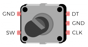
- Pinout: The KY-040 module has five pins:
- GND: Ground connection.
- VCC (+): Power supply input, typically 5V.
- SW: Output from the integrated push-button switch; active low.
- DT (Data): Output channel B.
- CLK (Clock): Output channel A.
Working Principle:
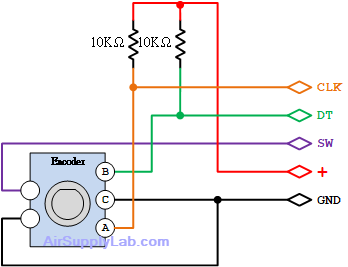
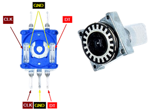
Inside the KY-040, a metal ring with small tabs is attached to the knob. As you rotate the knob, the metal ring also rotates, and the tabs intermittently make and break contact with the internal contacts. This action generates two pulse signals, one on each output channel (CLK and DT), which are slightly out of phase.
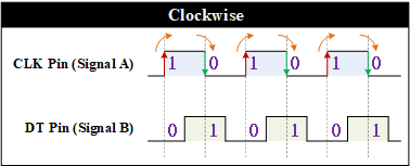
The CLK (Clock) and DT (Data) pins emit square wave pulses due to the physical contact of the tabs on the metal ring with the internal contacts. The phase difference between these pulses determines the direction of rotation:
- Clockwise Rotation: When turning clockwise, the CLK pulse leads to the DT pulse.
- Counter-Clockwise Rotation: When turning counter-clockwise, the DT pulse leads to the CLK pulse.
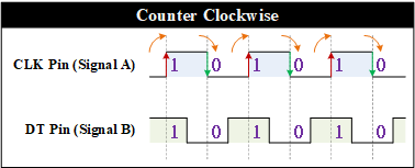
Each detent (a noticeable click or stop as the knob rotates) corresponds to one complete pulse cycle on both channels, which allows the microcontroller to count steps and determine the rotation's direction.
Application Notes
- Pull-Up Resistors: Some setups may require pull-up resistors on the CLK, DT, and SW pins to ensure stable readings.
- Debouncing: Mechanical contacts may cause bouncing, so software debouncing or low-pass filtering may benefit stability.
Required Reading Materials
- Lesson KB 01: Create a PSoC Project using PSoC Creator
- PSoC Creator Components
Required Components
If you use the Cypress CY8CKIT-059 Kit, the onboard LED and button will be used in this lab.
The following components are required for this lab.
 |
Push Button (Optional, can use onboard components) | x 1 |
| Resistor 200ohm (if using an external LED) | x 1 | |
| Red LED (or onboard LED) | x 1 |
Circuit / Schematic
Procedure
Creating a New Project
- Launch PSoC Creator.
- Got to File ➤ Open Project ➤ Project/Workspace.
- Open the PSoC5LP workspace in the EE4450 folder.
- After PSoC Creator opens the workspace, right-click on Workspace 'PSoC5LP' in the Workspace Explorer and select Add ➤ New Project….
- Select the correct PSoC5LP device model number, use the "Empty schematic" template, and enter the project name 16_RotaryEncoder.
Adding PSoC Creator Components
Open the "TopDesign.cysch" Schematic File, add the following components:
- Digital Output Pin:
- Navigate to the Ports and Pins catalog in the Component Catalog.
- Drag and drop the
 Digital Output Pin onto the schematic.
- Digital Output Pins:
- In the same Ports and Pins catalog.
- Drag and drop three</strong
 Digital Input Pin onto the schematic.
- Quadrature Decoder:
- Navigate to the Digital ➤ Functions catalog in the component selection panel.
- Find the
 Quadrature Decoder</span and drag it onto the schematic.
- PWM (Pulse Width Modulator):
- In the Digital ➤ Functions catalog, locate the
 PWM</span components.
 - Drag and drop the
 PWM</span onto the schematic.
- In the Digital ➤ Functions catalog, locate the
- Clock:
- Navigate to the System catalog in the component selection panel.
- Find the
 Clock</span component and drag it onto the schematic.
- Character LCD:
- Go to the Display catalog in the component selection panel.
- Find and drag the
 Character LCD onto the schematic.
- Logic Low (0):
- Go to the Digital ➤ Logic catalog in the component selection panel.
- Find and drag the
 Logic Low '0' onto the schematic.
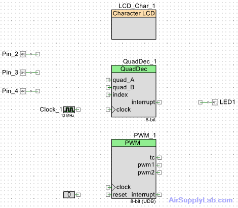
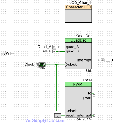
Once all components are placed, save the TopDesign.cysch schematic file. The completed TopDesign is displayed below:
Configure the Components
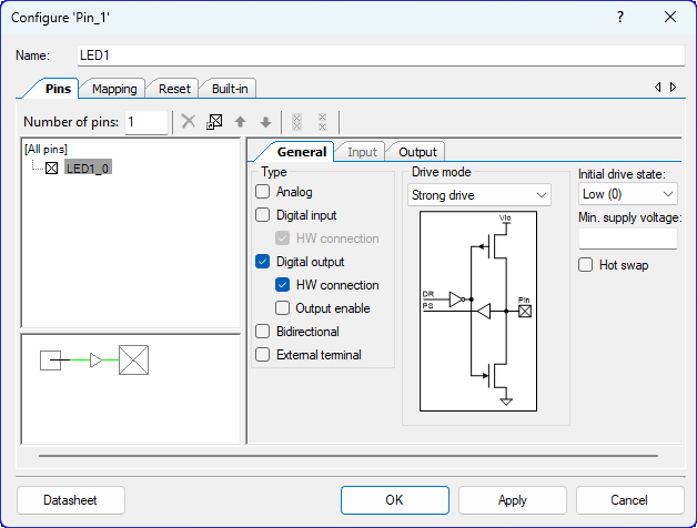
- Configure the Digital Output Pin (Pin_1):
- Select the Pin_1 component on the schematic.
- Rename the component to LED1</span to represent its connection to the onboard LED1.
- Configure the first Digital Input Pin (Pin_2):
- Select the Pin_2</span component on the schematic.
- Rename the component to Quad_A</span to represent its connection to the CLK pin of the KY-040 Decoder.
- Configure the second Digital Input Pin (Pin_3):
- Select the Pin_3</span component on the schematic.
- Rename the component to Quad_B</span to represent its connection to the DT pin of the KY-040 Decoder.
- Configure the Digital Input Pin (Pin_4):
- Select the Pin_4</span component on the schematic.
- Rename the component to nSW</span to represent its connection to the SW pin of the KY-040 Decoder sensor.
- Uncheck the box for ☐ HW connection box to disable the hardware connection. This step ensures that the pin will be controlled manually in the software.
- Change the Drive Mode to the Resistive pull up</span mode.
- Configure the Quadrature Decoder (QuadDec_1):
- Select the QuadDec_1</span component on the schematic.
- Rename the component to QuadDec</span for clarity and ease of identification.
- Change the tab to the Use Index Input, then uncheck the box ☐ Use index input.

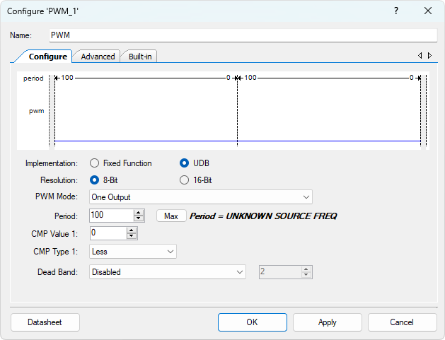
- Configure the PWM (PWM_1):
- Select the PWM_1 component on the schematic.
- Rename the component to PWM</span for clarity and ease of identification.
- Change the PWM Mode to One Output.
- Change the period</strong value to 100, and CMP Value</strong to 0.
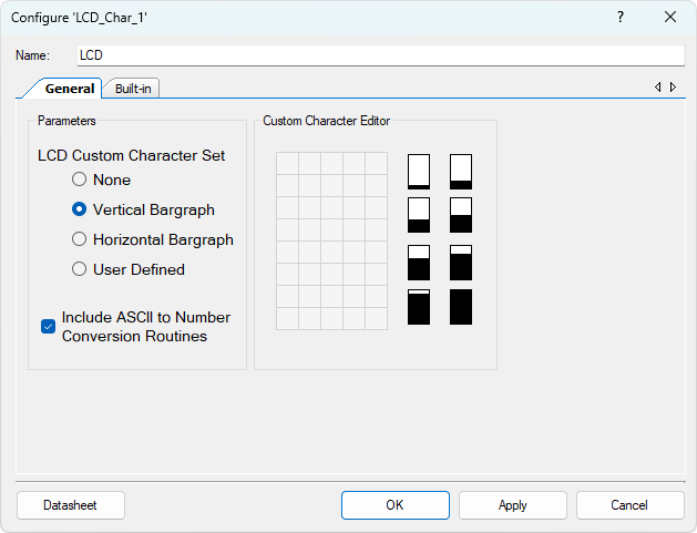
- Configure the Character LCD (LCD_Char_1):
- Select the LCD_Char_1 component on the schematic.
- Rename the component to LCD for clarity and ease of identification.
- In the General tab, select
 Vertical Bargraph.
Wiring
- Connect the Quad_A pin to the quad_A pin of the QuadDec component.
- Connect the Quad_B pin to the quad_B pin of the QuadDec component.
- Connect the LED1 pin to the pwm output of the PWM component.
- Connect the Clock_1 pin to the clock inputs of both the QuadDec and PWM components.
- Connect the Logic Low (0) to the reset pin of the PWM component.
Use this diagram to verify your connections and ensure everything is correctly wired according to the system design.
Pin Assignment
| Device | Port.Pin | Direction | Drive Mode |
|---|---|---|---|
Experiments
Implement a system that meets the following requirements:
- Initial Setup: Upon reset, initialize the PWM duty cycle to 0, resolution to x1, and counter value of the QuadDec to 0.
- Duty Cycle Calculation:
- The duty cycle ranges from 0 to 100.
- Calculate the duty cycle using the formula:
duty = counter × resolution - Different resolution settings correspond to different maximum counter values to ensure the duty cycle remains within the 0–100 range.
- QuadDec Counter Value Constraints:
- Ensure the QuadDec counter value remains within its allowable range based on the selected resolution setting, such that the calculated duty cycle does not exceed 100.
- Adjusting Duty Cycle with Encoder:
- Clockwise Rotation: When the user rotates the encoder clockwise, increment the duty cycle until it reaches a maximum of 100.
- Counterclockwise Rotation: When the user rotates the encoder counterclockwise, decrement the duty cycle until it reaches a minimum of 0.
- Changing Resolution:
- When the user presses and releases the encoder within a short duration (< 1 second), change the encoder resolution sequence — the resolution values cycle through x1, x2, x4, and x5.
- Resetting Duty Cycle with Long Press:
- When the user presses and holds the encoder for longer than 1 second, reset the duty cycle to 0. The resolution setting remains unchanged.
- Display on LCD:
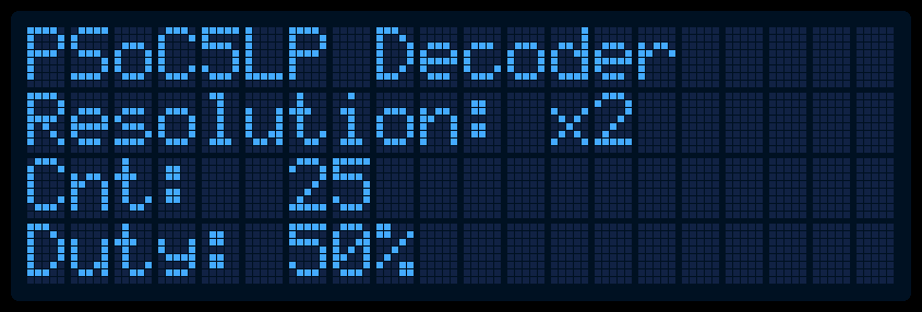
Display the QuadDec counter, PWM duty cycle, and resolution on the LCD as shown below: