KB 01: Create a PSoC Project using PSoC Creator
This lesson covers the following:
- Demonstrates how PSoC devices can perform tasks beyond traditional microcontrollers.
- Guides users on how to create, modify, program, and debug PSoC 5LP projects using PSoC Creator.
- Provides a step-by-step tutorial to simplify the learning of PSoC design techniques using the PSoC Creator IDE.
Reference DOCs
- PSoC Creator User Guide (V15.00)
- PSoC Creator Quick Start Guide (v18.00)
- PSoC5LP System Reference Guide (V5.90)
This lesson takes you through the design process step by step. It guides you through both hardware and firmware design entry.
1. Create a New Project
Create a New Project
A project in PSoC Creator contains all the source code and files necessary to generate a single output module that can be programmed onto a target PSoC 5LP device.
Start PSoC Creator
To launch PSoC Creator 4.x, follow one of these methods:
- From the Windows Desktop: Double-click the PSoC Creator icon.

- Launch PSoC Creator from the Windows Start Menu.
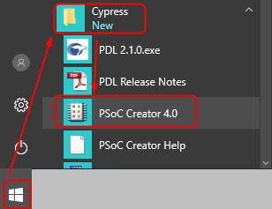
- From the Start Menu: Open the Windows Start Menu, search for "PSoC Creator," and click on it.
Create New Project
The first step in creating a design is to use the New Project Wizard in PSoC Creator. This wizard will guide you through the following steps:
- Select the kit, module, or device.
- Select the type of project to create
- Specify the project name and location
- Choose whether to create a new Workspace or add to an existing Workspace
Follow the next steps to open the wizard dialog and configure for a new project:
- Start a new project by either:
- Click the "Create New Project..." link on the PSoC Creator Start Page.
- Click the "Create New Project" button
 in the menu bar.
 - Selecting "File ➤ New ➤ Project ..." from the menu.
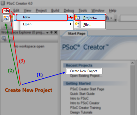
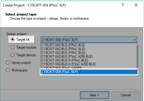
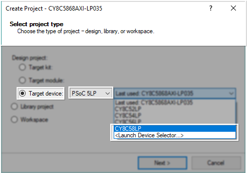
- In the Create Project dialog, select one of the following options:
- Target kit: Select a specific kit or the last used kit.
- Target module: Select a specific module or the last used module.
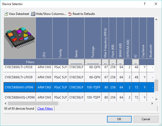
- Target device: Select a device family and series, the last used device, or launch the Device Selector.Selecting the kit, module, or device
- Select the Project Template:
Next, in the "Select project template" dialog, choose "Empty schematic" as your project template.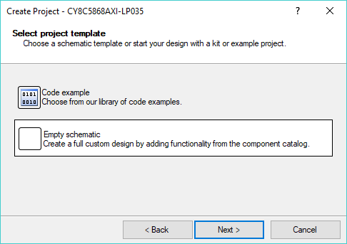
- Define Workspace and Project:
In the following dialog:
- Workspace name: Enter a name for your workspace (e.g., "PSoC5LP"). A workspace is a container for one or more projects.
- Location: Specify the path where the project will be saved, or click the "
 Browse" button to select a directory.
 - Project name: Enter a name for your project (e.g., "01_MyFirstPSoC").
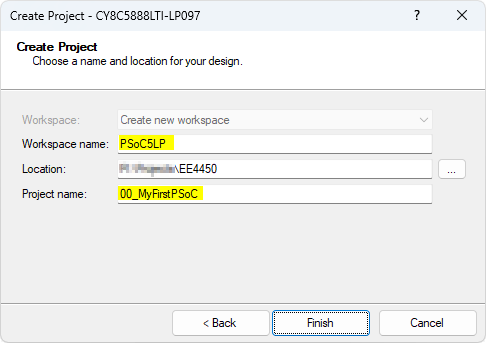
PSoC Creator organizes applications into Workspace that can contain one or more projects.
- Finalize Project Creation:
Click the Finish button. PSoC Creator will create a new directory based on the location you specified. Inside this directory, it will generate a subdirectory for the workspace, and within that, a folder for the project..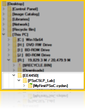
- Once the folders and files are created, the main PSoC Creator window will appear, displaying several panes:
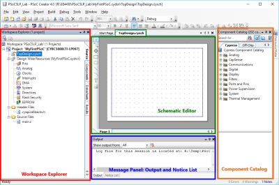
- Workspace Explorer: Displays all the files and folders in your project.
- Schematic Editor (TopDesign.cysch): Shows the top-level schematic for your design.
- Component Catalog: Lists the available components you can incorporate into your project.
- Message Panel: Displays build messages, errors, and warnings related to your project.
2. Device Selector
Device Selector
If you change the PSoC development board, follow these steps to update the microcontroller model:
- Expand the "Design Wide Resources (.cydwr)" folder in Workspace Explorer and double-click Pins to view the device pin assignments and the current device number.
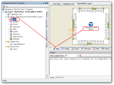
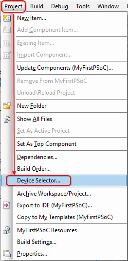
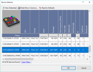
- Verify that the device number matches the one on your PSoC 5LP board. If not, go to the Project menu, select Device Selector, and choose the correct device.
- Once the correct device is selected, you won’t need to change it unless switching boards.
3. Add/Configure Component
Add/Configure Component
In this step, you will drag Components from the Component Catalog to the Schematic, configure them, and wire them together.
- Cypress Components: These are pre-installed and developed by Infineon for use in designs.
- Off-Chip Components: Represent external device connections for documentation.
Steps:
- In the Component Catalog panel, expand the "Digital ➤ Functions" folder and drag a PWM Component onto your TopDesign.cysch.
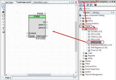
- Double-click the PWM Component to open the "Configure" dialog, change the Implementation setting to "Fixed Function", and click OK.
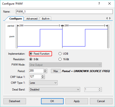
- In the Component Catalog, expand the "Digital ➤ Logic" folder, drag a Logic Low '0' Component onto your design, and connect it to the kill terminal on the PWM. Connect another Logic Low '0' to the reset terminal.
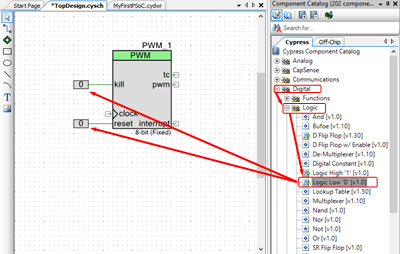
Select the Wire Tool to connect the logic (or press 『w' as a shortcut). The wire is Green, which means that it is a digital connection.
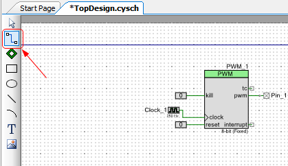
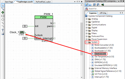
- In the Component Catalog, expand the "System" folder, drag a Clock Component onto your design, and connect it to the clock terminal on the PWM.
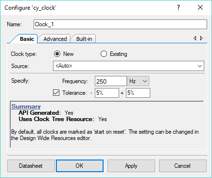
- Double-click the Clock to open the Configure dialog, change the Frequency value to 250 Hz, and click OK.
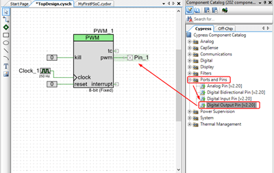
- Expand the "Ports and Pins" folder in the Component Catalog, drag a Digital Output Pin Component onto your design, and connect it to the pwm terminal on the PWM.
4. Assign Pins and Connect Hardware
Assign Pins and Connect Hardware
At this point, the hardware design is complete. However, the Pin Component must still be associated with a physical pin.
If you did not assign any pins, after you click Generate Application or Build your project from the Build menu, the PSoC Creator will automatically assign the pin to a physical port/pin on the device. To specify a specific pin, use the Pin Editor to assign the pin for the component.
- In the Workspace Explorer window, expand the "Design Wide Resources (.cydwr)" folder in your project and double-click on the Pins to open the Design Wide Resource (DWR) Pin Editor.
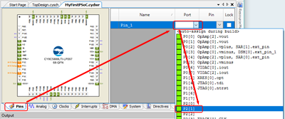
- Pull down the menu in the Port or Pin column and assign Pin_1 to the following pin, depending on the kit you are using:
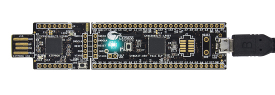
Cypress CY8CKIT-059 Kit
Cypress CY8CKIT-059 kit already has a switch and an LED on the board. The switch is connected to port 2, pin 2 (P2[2]), and the LED is connected to port 2, pin 1 (P2[1]). Therefore, for the CY8CKIT-059 Kit, you can assign Pin_1 to P2[1] (or Pin 63).

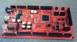
EagleSoC Development Board
EagleSoC Mini Board
- You will notice that many pins have some extra text associated with their port/pin information; for example, P1[2] is also labeled as 「XRES[0]:opt」. These special functions can be associated with the pin for improved performance rather than mandates that a given pin be used for a specific function.
5. Generate Application
Generate Application
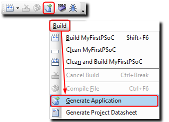
Before you write the code, you must let PSoC Creator generate all the necessary API files to support the hardware components you placed in the schematic earlier. Choose the "Generate Application" item in the Build function to do that.
- Select the PSoC Creator menu item Build➤Generate Application, or click the icon (
 ) on the toolbar.
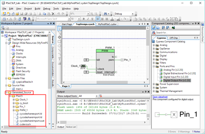
- If there is no error, PSoC Creator generates several code files under the folder Generated_Source. These are the support files for the components. Do not edit them. They are, in fact, just standard C files, and you could rework them to fit your needs, but the IDE can, and does, frequently regenerate those files, which would wipe out any changes you've made.
6. Add ezPSoCLib or Common Folder (Optional)
7. Write C Code
Write C Code
Add code to the auto-generated file main.c.
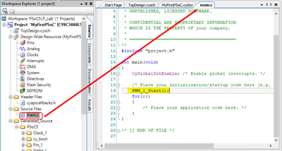
- In the Workspace Explorer panel, double-click the main.c file in your project to open it on the Document window.
- Add the following function to main():
PWM_1_Start();
This code assumes that the PWM Component has the default name. If you renamed your PWM Component to something other than the default value, use those names in the _Start() function call.
/* ========================================
 *
 * Copyright YOUR COMPANY, THE YEAR
 * All Rights Reserved
 * UNPUBLISHED, LICENSED SOFTWARE.
 *
 * CONFIDENTIAL AND PROPRIETARY INFORMATION
 * WHICH IS THE PROPERTY OF your company.
 *
 * ========================================
*/
#include "project.h"

int main(void)
{
    CyGlobalIntEnable; /* Enable global interrupts. */

    /* Place your initialization/startup code here (e.g. MyInst_Start()) */
    PWM_1_Start();
    for(;;)
    {
        /* Place your application code here. */
    }
}

/* [] END OF FILE */
8. Program the Device
Program the Device
The programming process is the same for all the development kit boards.
- Connect the programmer to your PSoC 5LP development board and plug it into your PC with a USB cable.
- Confirm that the programmer is connected to PSoC Creator through the USB port.
Select the PSoC Creator menu item Debug ➤ Select Debug Target... A "Select Debug Target" dialog is displayed
CY8CKIT-059 Kit
CY8CKIT-059 already has an onboard programmer, so plug the CY8CKIT-059 kit into your PC with a USB extension cable.
EagleSoC Development Board
It would be best to have an external programmer, such as MiniProg3 or EagleSoC Prog. Connect the programmer to your PSoC5LP board SWD Port and plug it into your PC with a USB cable.
If you are using the EagleSoC Boards, use a wire to connect the P0[0] pin to one of the four LEDs.
EagleSoC Mini Board
It would be best to have an external programmer, such as MiniProg3 or EagleSoC Prog. Connect the programmer to your PSoC5LP board SWD Port and plug it into your PC with a USB cable.
If you are using the EagleSoC Boards, use a wire to connect the P0[0] pin to one of the four LEDs.
- Click the Program button (
 ) in the menu bar.
 - Select your device if the Select Debug Target dialog displays, then click Connect and OK.
PSoC Creator will build your design, generate code, and program the device. When programming is complete, the selected LED on the board will blink; press the Reset button if needed.
