Lab 15: Matrix Keypad
Objective
Overview
Required Reading Materials
- Lesson KB 01: Create a PSoC Project using PSoC Creator
- Datasheets:
- PSoC Creator Components
Required Components
The following components are required for this lab.
 |
4x4 Matrix Keypad | x 1 |
| Character LCD Module (4 x 20) | x 1 |
Circuit / Schematic
Procedure
Creating a New Project
- Launch PSoC Creator.
- Got to File ➤ Open Project ➤ Project/Workspace.
- Open the PSoC5LP workspace in the EE4450 folder.
- After PSoC Creator opens the workspace, right-click on Workspace 'PSoC5LP' in the Workspace Explorer and select Add ➤ New Project….
- Select the correct PSoC5LP device model number, use the "Empty schematic" template, and enter the project name 15_MatrixKeypad.
Adding PSoC Creator Components
Open the "TopDesign.cysch" Schematic File, add the following components:
- Add a Digital Output Pins:
- Navigate to the Ports and Pins category in the Component Catalog.
- Drag and drop the
 Digital Output Pin onto the schematic.
- Add a Digital Input Pins:
- In the same Ports and Pins catalog.
- Drag and drop the
 Digital Input Pin onto the schematic.
- Add a Character LCD component:
- Go to the Display catalog in the component selection panel.
- Find and drag the
 Character LCD onto the schematic.
Configure the Components
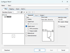
- Configure the Digital Output Pin (Pin_1):
- Select the Pin_1 component on the schematic.
- Rename it to KEYPAD_ROWS to represent its connection to the keypad rows.
- Uncheck the ☐ HW connection box to disable the hardware connection. This step ensures that the pin will be controlled manually in the software.
- Set the Number of pins to 4 and select all pins.
- Change Drive Mode to Open drain, drive high.

- Config the Digital Input Pin (Pin_2):
- Select the Pin_1 component on the schematic.
- Rename the component to KEYPAD_COLS to represent its connection to the keypad columns.
- Uncheck the ☐ HW connection box to disable the hardware connection. This step ensures that the pin will be controlled manually in the software.
- Set the Number of pins to 4 and select all pins.
- Change Drive Mode to Resistive pull down.

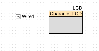
- Config the Character LCD (LCD_Char_1):
- Click on the LCD_Char_1 component in the schematic.
- Rename it to LCD for easy identification.

After these configurations, the updated TopDesign.cysch file will reflect these changes. Save the schematic to confirm the setup.

Pin Assignment
| Device | Port.Pin | Direction | Drive Mode |
|---|---|---|---|
Building the code and Programming
Firmware Template:
/* ========================================
 *
 * © 2024 AirSupplyLab. All rights reserved.
 * Unpublished, licensed software.
 *
 * This software contains confidential and proprietary
 * information owned by AirSupplyLab.com.
 *
 * ========================================
*/
#include "project.h"      // Include project-specific header files
#include <stdio.h>        // Standard library for input/output operations
#include <stdlib.h>       // Standard library for general-purpose functions
#include <stdint.h>       // Standard library for fixed-width integer types
#include <stdbool.h>      // Standard library for boolean data type

void ReadKeypad();        // Function prototype for keypad reading function

int main(void)
{
    char            key;          // Variable to store the key pressed
    char            str[50];      // Buffer to store strings for LCD output
    int32_t         value = 0;    // Variable to store numeric input
    unsigned int    i;            // Variable for loop counters or general use

    CyGlobalIntEnable; /* Enable global interrupts. */

    /* Place your initialization/startup code here (e.g. MyInst_Start()) */
    LCD_Start();
    LCD_ClearDisplay();
    LCD_Position(0,0);
    LCD_PrintString("PSoC5LP Keypad");
    CyDelay(1000);

    for(;;) {
        /* Place your application code here. */
        ReadKeypad();

        // Write your solution code here

        CyDelay(20);
    }
}
//------------------------------------------------------------------------------
char    KeyPad[][4] = {
                {'1', '2', '3', 'A'},
                {'4', '5', '6', 'B'},
                {'7', '8', '9', 'C'},
                {'*', '0', '#', 'D'} };
#define _BIT0   0x01
#define _BIT1   0x02
#define _BIT2   0x04
#define _BIT3   0x08
#define _BIT4   0x10
#define _BIT5   0x20
#define _BIT6   0x40
#define _BIT7   0x80

void ReadKeypad()
{
    int         i, j, row, col;
    char        ch;

    // Implete scan method to scan keypad

}
/* [] END OF FILE */
Exercises
Exp #02:
In this lab, you will design an embedded system to meet the following requirements:
Functional Requirements:
- Display Key Presses:
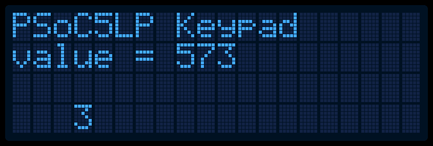
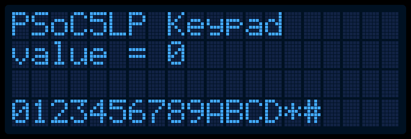
- When the user presses any key on the keypad, the character will be displayed on the last row of the LCD screen.
- The character should only be visible while the key is pressed. Once the key is released, the LCD will clear the character from the display.
- Variable Manipulation:
- The system will maintain an integer variable named value, initialized to 0.
- When the user presses numeric keys (0 to 9), the system will:
- Add the numeric value of that key to "value"
- Update the LCD to display the new "value"
- Special Key Functions:
- Clear (* key): When the * key is pressed, reset "value" to 0., and display this updated value on the LCD.
- Multiply by 10 (# key): When the # key is pressed, multiply the current value by 10 and display this updated value on the LCD.

