Lesson 00: General Requirements for Tiva Laboratories
You will learn the ARM architecture in this session. You must purchase some hardware components and a development board and install all the necessary software (please see the detail below) on your PC (or Laptop) with a USB interface that runs on the Microsoft Windows 64-bit platform. Maybe you need a USB HUB with an external power source to provide enough current to the embedded system.
Components Required
You must have a TI Tiva C Series LaunchPad board and other components. I recommend you get TI EK-TM4C123GXL Board and Elegoo Complete Starter Kit. Some of the components in the kit may not be used in the "Tiva Lab," but they will be used for PSoC projects, or you can use it with other microcontrollers.
The TI Tiva LaunchPad is an evaluation platform introduced by Texas Instruments for their Tiva C Series microcontrollers. These microcontrollers are ARM Cortex-M4F-based MCUs designed for various industrial, automotive, and consumer electronics applications. The LaunchPad has built-in peripherals, making it easy for developers to prototype and test their applications. With onboard emulation for programming and debugging and the support of TI's extensive software ecosystem, the Tiva LaunchPad provides an affordable and accessible entry point for embedded system development.
You can use EK-TM4C123GXL or EK-TM4C1294XL board and purchase it from ti.com or other vendors.
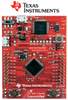
EK-TM4C123GXL LaunchPad
Texas Instruments TM4C123GXL Tiva C Series LaunchPad Evaluation Board
- Tiva TM4C123GH6PMI 80MHz 32-bit ARM Cortex-M4 based MCU with floating point
- 256KB Flash / 32KB SRAM / 2KB EEPROM on-chip memory
- Dual 12-bit ADCs (1MSPS)
- 6x 64-bit and 6x 32-bit timers
- Advance MC PWMs (16 PWM outputs)
- 4x I2C ports, 8x UARTs, 4x SSI modules, 2x CANs 2.0 A/B
- USB micro-A and micro-B connectors for USB on-the-go (OTG)/Host/Device connectivity
- On-board RGB user LED
- Two user switches (application/wake)
- Switch-selectable power sources
- ICDI
- USB device
- Reset switch
- Tiva C Series TM4C123G LaunchPad BoosterPack XL interface, which features stackable headers to expand the capabilities of the Tiva C Series LaunchPad development platform
Order
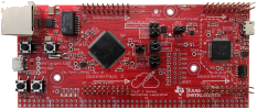
EK-TM4C1294XL LaunchPad
TM4C1294 Tiva C Series LaunchPad Evaluation Board
- TM4C1294NCPDTI 120MHz 32-bit ARM Cortex-M4 MCU with floating point
- 1MB Flash / 256KB SRAM / 6KB EEPROM on-chip memory
- 10/100 Ethernet MAC + PHY
- 8x 32-bit (16x 16-bit) timers
- Dual 12-bit ADCs (2 MSPS)
- Advanced motion control PWMs
- 10x I2C ports, 8x UARTs, 4x quad SSIs, 2x CANs, USB 2.0 port with HS ULPI
- Two BoosterPack XL interfaces (2x40 pin) each with stackable
- 2× user buttons, wake and reset buttons, plus 4 user LEDs and power-indicator LED
- Integrated USB-powered in-circuit debug interface (ICDI)
- RJ-45 Ethernet jack
- Jumper-selectable power sources
- BoosterPack
- OTG
- ICDI
- USB Host/Device port
Order
RobotSoC Starter Kit
You can purchase The RobotSoC Starter Kit for Embedded Projects from RobotSoC.com (here).
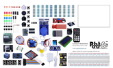
- This kit has 63 parts (more than 200 components) that are packaged in a convenient container.
- All the modules come soldered so they are easy to wire up
The kit includes the following components:
- 5pcs White LED
- 5pcs Yellow LED
- 5pcs Blue LED
- 5pcs Green LED
- 5pcs Red LED
- 1pcs RGB LED
- 5pcs 22pf Ceramic Capacitor
- 5pcs 104 Ceramic Capacitor
- 2pcs Photoresistor
- 1pcs Thermistor
- 5pcs Diode Rectifier (1N4007)
- 2pcs Electrolytic Capacitor (10UF 50V)
- 2pcs Electrolytic Capacitor (100UF 50V)
- 5pcs NPN Transistor (PN2222)
- 5pcs NPN Transistor (S8050)
- 1pcs Tilt Switch 5pcs Button (small)
- 1pcs 1 digit 7-segment Display
- 1pcs 4 digit 7-segment Display
- 1pcs Sound Sensor Module
- 1pcs Character LCD Module 20×4
- 1pcs IC L293D
- 1pcs IC 74HC595
- 1pcs Active Buzzer
- 1pcs Passive Buzzer
- 1pcs RTC Module
- 1pcs DHT11 Temperature and Humidity Module
- 2pcs Potentiometer 10K ohm
- 1pcs Rotary Encoder Module
- 1pcs Joystick Module
- 1pcs Keypad Module
- 1pcs 5V Relay
- 1pcs IR Receiver Module
- 1pcs Breadboard
- 1pcs Servo Motor (SG90)
- 1pcs Stepper Motor
- 1pcs ULN2003 Stepper Motor Driver Board
- 1pcs Power Supply Module
- 1pcs HC-SR501 PIR Motion Sensor
- 1pcs Ultrasonic Sensor
- 1pcs ADXL335 Module
- 1pcs 3V Servo Motor
- 1pcs MAX7219 Module
- 1pcs Remote
- 1pcs 9V 1A Power Supply
- 1pcs 65 Jumper Wire
- 1pcs Water Lever Sensor
- 1pcs USB Cable
- 1pcs 9V Battery Cable
- 1pcs RC522 RFID Module
- 10pcs Resistor (10R)
- 10pcs Resistor (100R)
- 10pcs Resistor (220R)
- 10pcs Resistor (330R)
- 10pcs Resistor (1K)
- 10pcs Resistor (2K)
- 10pcs Resistor (5K1)
- 10pcs Resistor (10K)
- 10pcs Resistor (100K)
- 10pcs Resistor (1M)
- 20pcs Female-to-male Wire Cables
Jumper Wires and Connector Housings
Jumper Wires and Connector Housings
Here, I recommend you purchase some colors of jumper wires and housings.
The color wires help you to keep track of your connections and avoid connection errors, such as short-circuit connections, reverse power connections, etc. For example, always use black wire for ground and red wire for power, so you will easily and quickly recognize the power source wires, and make sure they are not connected together, and that there is no reverse connection to the power supply sources.
The connector housings can help you to organize connection wires. Using connector housings with color jumper wire can help you to easily reconnect the devices without having to connect each wire every time, and reduce connection errors.
Jumper Wires
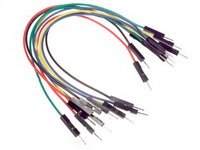
You will need jumper wires for making quick and easy prototyping connections between sensors, the breadboard, and the embedded board. Use them to wire up all the circuits.
Jumper wires can be purchased with male terminations on both ends, female terminations on both ends, or one male and one female termination. These terminations are designed for use with 0.1" (2.54 mm) male headers and female headers, solderless breadboards, and prototyping PCBs. The wires are available in various lengths and colors. The 3" (7.5 cm) wires are useful for the connections on the breadboard; the 6" (15 cm) wires are useful for the connections between the embedded board and breadboard; the 12" (30 cm) wires are useful for the connections between the sensor and breadboard/embedded board.
Here, recommend you prepare all there types of wires in various lengths for the embedded labs:
- Female-Female Jumper Wires: 6", 12"
- Male-Female Jumper Wires: 6", 12"
- Male-Male Jumper Wires: 3", 6"
Buy jumper wires from Pololu - Premium Jumper Wires.
Does the color of Jumper Wires matter?
No, the colors do not matter. The wire color is just an aid to help you keep track of which connections are connected and do not affect the operation of the circuit. You can define your own color-coding scheme, but here we recommend you to follow the rules as below lists, so everybody can understand the way the circuit is wired:
- Black Wire: Negative Power Sources (GND)
- Brown Wire: Data signals
- Red Wire: Positive Power Sources (+5V)
- Orange Wire: In a dual power source circuit, orange wires are used for +3.3V power sources. Otherwise, it can be used for Data signals
- Yellow Wire: Clock Signals
- Green Wire: Protective earth ground (PG)
- Blue Wire: Data signals
- Purple Wire: Reset Signals
- grey Wire: In the mixed signals circuit, use grey wires for Analog Ground (AGND); Otherwise, it can be used for Data signals
- White Wire: for Data signals
Crimp Connector Housings
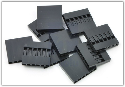
Connector housings allow you to quickly make up your own custom cable harnesses or assemblies for connection to your hardware circuit projects. It mates with various 0.1" (2.54 mm) - spaced connectors, including male and female headers and solderless breadboards. Just select the housing with the correct number of pins, pick the colors and genders for your wires, and snap them into the housings.
I recommend using the housing to make some cables, so you can quickly reconnect the devices without checking all of the wire connections one by one every time. The connector housings can use with pre-crimped wires, which are "jumper wires" you purchase from Pololu, or you can make your own self-crimped wires with the crimping tool.
At least, you need the following housings for the embedded Labs:
- 0.1" (2.54mm) Crimp Connector Housing: 1x2-Pin
Power Connections - 0.1" (2.54mm) Crimp Connector Housing: 1x3-Pin
PIR Sensor, Servo, IR Receiver Module, DHT11 Module, Water Level Sensor, - 0.1" (2.54mm) Crimp Connector Housing: 1x4-Pin
I2C devices, Stepper Motor Driver Board, Ultrasonic Sensor, Sound Sensor - 0.1" (2.54mm) Crimp Connector Housing: 1x5-Pin
Joystick, Rotary Encoder Module, Matrix LEDs Module - 0.1" (2.54mm) Crimp Connector Housing: 1x6-Pin
SPI Devices, - 0.1" (2.54mm) Crimp Connector Housing: 1x8-Pin
RC522 RFID Module, MPU Module - 0.1" (2.54mm) Crimp Connector Housing: 1x16-Pin
Character LCD module
You can buy the housings from the following vendors:
Software Required
Please download and install the following software onto your computer.
- ARM Keil
- MDK-Arm 5.x IDE: https://www.keil.com/download/product/
- Stellaris ICDI Debug Adapter Support: MDK_Stellaris_ICDI_AddOn.exe
- TI Stellaris ICDI Driver (SW-ICDI-DRIVERS): http://www.ti.com/tool/STELLARIS_ICDI_DRIVERS
- (Optional) TI TivaWare for C Series Complete (SW-TM4C): http://www.ti.com/tool/sw-tm4c
- ICDI Firmware Tools (for trouble-shooting used):
The development software is only working on the Microsoft Windows platforms. If you are using an Apple Mac computer, you need to install virtual machine software (VirtualBox, Fusion for Mac, Parallels) on the macOS X, and install Microsoft Windows on the Virtual Machine, then install all necessary software in the virtual Windows system.
Documents
The following documents provide detailed data about the TI Tiva LaunchPad board and microcontroller. Please download all of them to your local driver for reference.
EK-TM4C123GXL LaunchPad
EK-TM4C1294XL LaunchPad
Useful Resources
The following websites provide a lot of useful information about TI Tiva LaunchPad.
