Lesson 04: System Clock
PSoC Creator Component Datasheet: cy_clock_v2_20.pdf
The PSoC 5LP clocking system is responsible for generating, dividing, and distributing clocks throughout the system. It offers flexibility to optimize for accuracy, power, and cost, and is configurable via the PSoC Creator IDE.
4.1 Clock Sources and General Features
Clock Sources and General Features
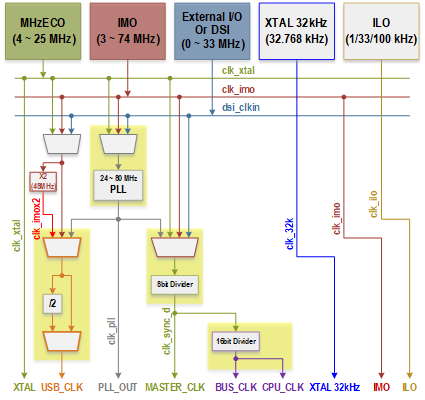
Figure 4.1: PSoC 5LP Clock Propagation Diagram
Internal Oscillators:
- Internal Main Oscillator (IMO):
- The primary clock source for most designs, providing stable output frequencies without external components.
- Factory trimmed, the IMO's accuracy varies from ±1% at 3 MHz to ±7% at 74 MHz
- No external components required
- Often used with PLL for higher frequencies
- It outputs at frequencies of 3 MHz ±1%, 6 MHz ±2%, 12 MHz ±3%, 24 MHz ±0.25%, 48 MHz ±5%, 62.6MHz ±7% and 74.7 MHz ±7%
- Internal Low-Speed Oscillator (ILO):
- Generates 1 kHz, 33 kHz, and 100 kHz frequencies
- 1 kHz is used for the central timewheel, 100 kHz for the fast timewheel, and 33 kHz as a reduced accuracy version of the ECO clock.
- Used for low-power operations (watchdog timer, sleep timer, timewheels)
External Oscillators:
- MHz External Crystal Oscillator (MHzECO, XTAL):
- Utilizes an external crystal for high-precision
- 4 ~ 25 MHz, high precision with external crystal
- Used with PLL for high-frequency, high-accuracy systems
- It can generate CPU and system clocks up to the device's maximum frequency when used with the PLL
- 32.768 kHz External Crystal Oscillator (XTAL 32kHz):
- Used for RTC
Clock Generation and Distribution:
- Clock Doubler:
- Doubles the frequency of an input clock
- Typically used for the USB block, it operates at an input frequency of 24 MHz to provide 48 MHz
- Phase-Locked Loop (PLL):
- Multiplies low-frequency clocks to higher frequencies
- Phase lock achieved within 250 μs
- 24 ~ 80 MHz output, 4032 discrete ratios
- Used with IMO or MHzECO
- Disable before entering low power modes
- Clock Dividers:
- 8 general-purpose 16-bit clock dividers
- Dedicated divider for CPU bus and CPU clock
Automatic Clock Configuration:
PSoC Creator IDE allows automatic configuration of the clocking system based on overall system requirements. Designers specify desired frequencies and accuracies, and the software configures the clocks accordingly.
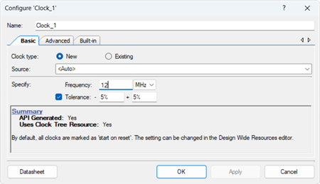
Figure 4.2: Clock Configuration
Guidelines for Implementation:
- Select Clock Sources: Choose the appropriate internal and external clock sources based on your system's requirements.
- Configure Clocks in PSoC Creator: Use the PSoC Creator IDE to specify clock frequencies and accuracies.
- Consider Power and Accuracy: Balance the need for high clock frequency and accuracy with power consumption considerations.
- Use PLL for Higher Frequencies: Employ the PLL to multiply lower frequency clocks from the IMO or MHzECO to higher frequencies as needed, considering the trade-off between frequency, accuracy, and power consumption.
- Implement Clock Dividers: Utilize the 16-bit clock dividers to generate specific frequencies for different parts of your system, like a UART baud rate generator.
- Manage Power Modes: Remember to disable the PLL before entering low-power modes to conserve energy.
Steps for Clock System Setup:
- Determine System Requirements: Identify your application's clock frequency and accuracy requirements.
- Select Clock Sources: Choose from the internal oscillators (IMO, ILO) or external oscillators (MHzECO) based on your needs.
- Configure PLL (if needed): Use the PLL for generating higher frequencies from a stable, low-frequency source. Configure the PLL settings in the PSoC Creator IDE.
- Set Up Clock Dividers: Use the 16-bit clock dividers to create specific clock frequencies for various subsystems.
- Configure Clock Doubler (for USB): If your system includes a USB block, configure the clock doubler to provide the required frequency.
- Adjust for Low Power Consumption: If your application demands low power, consider using the ILO and managing clock frequencies and operational modes accordingly.
- Finalize Configuration in PSoC Creator: Once all clock sources and settings are selected, finalize your configuration in the PSoC Creator IDE. The software will automatically arrange the clocking system based on your inputs.
After configuring the clock system, thoroughly test your PSoC device to ensure all clocks function as expected under various operating conditions and modes.
The PSoC 5LP clocking system offers a versatile and programmable approach to managing system clocks. By understanding and utilizing its features, designers can effectively tailor the clocking system to meet the specific needs of their applications, balancing performance, power consumption, and cost.
Table 4.1: Oscillator Summary
| Source | ƒmin | ƒmax |
|---|---|---|
| IMO | 3 MHz | 74.7 MHz |
| ILO | 1 kHz | 100 kHz |
| MHzECO | 4 MHz | 25 MHz |
| kHzECO | 32.768 kHz | |
| PLL | 24 MHz | 80 MHz |
4.2 Configuration System Clock in PSoC Creator
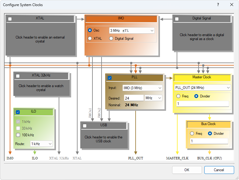
Figure 4.3: PSoC Creator "Configure System Clocks" Dialog
The PSoC 5LP clocking system is a critical part of your design, dictating the timing and operation of various components. The 'Configure System Clocks' dialog in PSoC Creator provides a graphical representation of the system clocks and their relationships, helping to simplify configuration.
Access the Configure System Clocks Dialog:
- Open your project in PSoC Creator.
- Navigate to the Design-Wide Resources (DWR) tab.
- Locate the "Clocks" section and click the "Configure System Clocks" button.
Understand the Graphical Diagram:
- Clock Enablement: A checkmark indicates an enabled clock. Grayed-out clocks are disabled, and some cannot be disabled.
- Clock Paths: Lines show potential clock signal routes. Gray lines represent inactive paths in the current configuration.
- Error Indicators: Red error icons
 highlight incorrect configurations. Hover over the icon for a detailed message.
Master Clock and Bus Clock:
- Master Clock: The primary source for generating all other PSoC clocks (including bus clock). It has the highest or equal frequency to all other PSoC clocks.
- Bus Clock: Derived from the master clock and serves as the clock source for the CPU, DMA, DFB, and other major blocks. It usually operates at the same frequency as the Master Clock but serves different functions.
Configuration Steps:
- Select Clock Sources: Choose appropriate clock sources (IMO, PLL, ECO, etc.) based on your system's requirements for frequency and accuracy.
- Enable/Disable Clocks: Check/uncheck boxes to enable or disable specific clocks.
- Adjust Clock Settings: Modify clock frequencies, dividers, and other settings as needed.
- Resolve Errors: Address any errors indicated by red icons.
- Review Configuration: Carefully examine the diagram and settings to ensure they align with your design goals. After making necessary adjustments, review the entire clock configuration to ensure all components are correctly synchronized.
- Rebuild Project: Save your configuration and recompile the project to apply the changes.
Testing and Validation:
- Test your design to confirm that all components function as expected with the new clock configuration.
- Pay special attention to timing-sensitive components to ensure they operate correctly with the adjusted clock settings.
Device-Specific Variations:
- The available clocks and options within the dialog may differ depending on the specific PSoC 5LP device you're using.
- Some devices may organize the dialog into tabs for high-frequency and low-frequency clocks.
Additional Considerations:
- Power Consumption: Higher clock frequencies generally consume more power.
- Accuracy: Select clock sources and PLL settings to achieve the required accuracy for your application.
- USB: For USB functionality, use either the IMO in USB mode or the Clock Doubler with a 24 MHz input.
- Low-Power Modes: Disable the PLL and use the ILO for low-power operations.
Proper configuration of the PSoC 5LP clocking system is crucial for the optimal performance of your design. Taking the time to accurately set up and verify each clock ensures your system runs reliably and efficiently.
XTAL
The XTAL Configuration dialog in PSoC Creator is used to set up the characteristics of the external crystal oscillator (XTAL) for precise frequency control and stability.
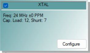
Access the XTAL Configuration Dialog:
- In PSoC Creator, open the "Configure System Clocks" dialog (located on the Design-Wide Resources tab).
- Enable the XTAL clock by checking its box.
- Click the "Configure" button next to the XTAL clock.
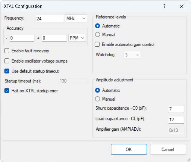
Configure XTAL Settings:
- Frequency/Accuracy:
Enter the precise frequency and accuracy of your crystal. - Enable Fault Recovery (Optional):
- Check this box to activate fault recovery, which switches to the IMO if the XTAL malfunctions.
- Note: Not compatible with XTAL sourcing IMO.
- Enable Oscillator Voltage Pumps (Optional):
- Use this option to control the oscillator voltage pumps through the FASTCLK_XMHZ_CSR register.
- Check this box to reduce power consumption and jitter potentially.
- By default, this is not enabled.
- Use Default Startup Timeout:
- This option, selected by default, uses the system’s default timeout at startup.
- Uncheck this box to specify a custom timeout (in milliseconds) based on your XTAL's requirements.
- Halt on XTAL Startup Error:
- Check this box to halt the application before main() if the XTAL fails to start.
- Uncheck this box to handle the error within your code.
- Note: This setting is ignored if the XTAL does not source the bus clock.
- Reference Levels (Advanced Users): Choose between automatic or manual reference level configuration:
- Automatic: Selected by default. Automatically calculates reference levels from the specified XTAL frequency, which are then used to set the CFG1 register during XTAL clock initialization.
- Manual: For advanced users. Allows manual adjustment of Feedback and Watchdog levels for fine-tuning the reference level configuration.
- Enable Automatic Gain Control (AGC): Not selected by default. AGC adjusts the oscillation amplitude of the XTAL to match a reference value, optimizing the drive level. The Feedback field becomes visible beneath Watchdog when AGC is enabled.
- Watchdog Reference Level:
- Sets the voltage threshold for oscillation amplitude detection.
- The watchdog, also known as XERR or error detection, monitors oscillation amplitude.
- If amplitude falls below a threshold, it triggers an error signal and can optionally activate fault recovery.
- It is essential for ensuring oscillation stability and reliable clock operation.
- Feedback Reference Level:
- Used for amplitude comparison within the AGC feedback loop.
- Use this field to specify the reference voltage level for oscillation amplitude comparison.
- This setting helps fine-tune the XTAL performance, ensuring it operates within the desired thresholds.
- Watchdog Reference Level:
- Amplitude Adjustment: Choose between automatic or manual amplitude adjustment:
- Automatic: Default selection. Automatically calculates Amplifier Gain (AMPIADJ) based on the XTAL frequency and specified shunt and load capacitance. This value is used to set the CFG0 register.
- Manual: For advanced users. Allows manual input of the Amplifier Gain (AMPIADJ) value for the CFG0 register.
Review and Apply:
- After configuring all necessary fields, click "OK" to apply the settings.
- Review your configuration to ensure it aligns with your system requirements and the XTAL specifications.
- Save and recompile your project to apply the new XTAL configuration.
Testing and Validation:
- Test the system to ensure the XTAL operates correctly under the configured settings.
- Pay close attention to system behavior at startup and under different operational conditions to validate fault recovery and error handling as configured.
Proper configuration of the XTAL in the PSoC 5LP is crucial for maintaining accurate system timing. The flexibility of PSoC Creator allows for precise control over the external crystal's characteristics, ensuring optimal performance of your system.
24 MHz Crystal
| Component | Description | Manufacturer | Manufacturer Part No |
|---|---|---|---|
| 24 MHz Crystal | CRYSTAL 24.000MHZ 20PF SMD | ECS Inc | ECS-240-20-5PX-TR |

Electrical Characteristics
| Parameters | Conditions | Min | Typ | Max | Units |
|---|---|---|---|---|---|
| Frequency Tolerance | @ +25 ºC | ± 30 | ppm | ||
| Frequency Stability | Standard -10 ~ +70 ºC |
± 50 | ppm | ||
| Shunt Capacitance | C0 | 7 | pF | ||
| Load Capacitance | CL | 20 | pF | ||
| Drive Level | DL | 500 | µW | ||
| Operating Temperature | Topr | -10 | +70 | ºC | |
| Equivalent Series Resistance (ESR) | 20 MHz ~ 40 MHz | 30 | Ω |
32.768 kHz XTAL
| Component | Description | Manufacturer | Manufacturer Part No |
|---|---|---|---|
| 32.768KHz XTAL | CRYSTAL 32.768 KHZ CYL 12.5PF CFS308 | Citizen America Corp. | CFS308-32.768KDZF-UB |

| Parameters | Conditions | Min | Typ | Max | Units |
|---|---|---|---|---|---|
| Frequency Tolerance | Δƒ / ƒ0 @ +25 ºC | ± 20 | ppm | ||
| Shunt Capacitance | C0 | 1.60 | pF | ||
| Load Capacitance | CL | 12.5 | pF | ||
| Drive Level | DL | 1 | µW | ||
| Operating Temperature | Topr | -10 | +60 | ºC | |
| Equivalent Series Resistance (ESR) | R1 | 35 | kΩ |
IMO
...
Digital Signal
...
XTAL 32kHz
...
PLL
...
Master Clock
...
Bus Clock
...
ILO
...
USB
...