Matrix Keypad
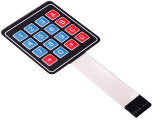
Keypads are used in all types of devices, including cell phones, fax machines, microwaves, ovens, door locks, etc. They are practically everywhere. The tone of electronic devices uses them for user input.
In this section, we will discuss the logic and interface of a matrix keypad with a microcontroller to reduce the number of port pins required to read a certain number of digital inputs. The same logic applies to any matric keypad.
Why Matrix Keypad?
Typically, one digital input is connected to one port pin. When there are a lot of digital inputs that have to be read by the microcontroller, it requires the same number of port pins to read each input signal separately. It would not be feasible to allocate one pin for each of them, because these will occupy a lot of I/O pins. the main reason is that microcontrollers grow with the number of pins, and growth means more power, capabilities, and most of all higher prices. So in the end you can either get a cheap chip with little capabilities (that is what you need) but with few I/O pins, or a more powerful chip, which is much more than you need.
Therefore, a new interface technique will be needed to reduce the number of required pins in this kind of situation. The easiest way to do that is to arrange inputs in matrix form, which divides I/O pins into two sections: the rows and the columns. For example, a 64-key keyboard would require 64 digital input port pins. With a matrix circuit, 16 I/O pins arranged in 8 rows and 8 columns can connect 64 keys — 8 output pins to drive rows and 8 input pins to read columns.
What are the Key Matrices?
The Matrix Keypad is made by arranging push button switches in rows and columns. If you want to interface a 4 by 4 (16 keys) matrix keypad with a microcontroller. In a straightforward way, you will need 16 I/O pins of a microcontroller for that, but by using a simple technique we can reduce it to 8 I/O pins. In the matrix keypad, switches are connected in a special manner as shown in the figure below.
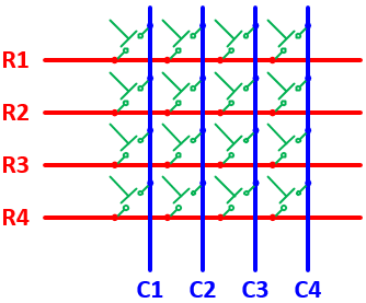
The blue lines are the columns and the red lines are the rows. There are 16 knots that the rows and columns intersect, and each knot connects one switch button. There will be no connections between columns and rows. When any of the switches are pressed, the corresponding columns and rows are connected (short-circuited), which can be detected by the microcontroller to identify which keys have been pressed.
How Does Key Matrix Work?
We make the columns as input pins and we drive the rows making their output pins. In order for the microcontroller to determine which button is pressed, it first needs to pull each of the four rows (R1 ~ R4) either logic low or high one at a time and then poll the states of the four columns (C1 ~ C4). Depending on the states of the columns, the microcontroller can detect which button is pressed.
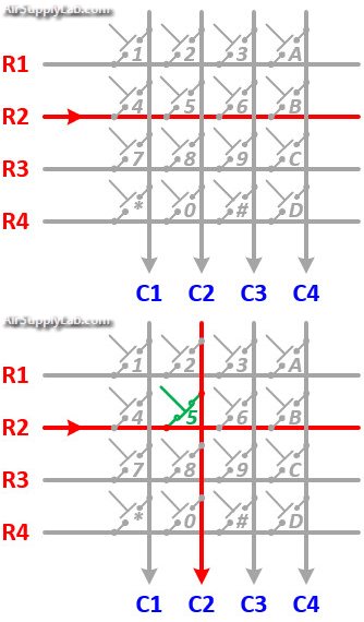
Let us assume that a logic high signal is given to Row 2 (R2). If any of the keys belonging to Row 2 is pressed, the high signal from Row 2 will pass to the corresponding column as high. Watch the above animation, the button '5' is pressed, then column 2 will also be high as long as the button '5' is pressed. What this means is that if we know which row has currently logic high signal, and we watch the columns, then we can understand which button was pressed, if we detect power on a column. For example, our program pulls all four rows low and then pulls the second row (R2) high. It then reads the input states of each column and reads column 2 high. This means that a connection has been made between column 2 and row 2, so button '5' has been pressed.
4x4 Matrix Keypad Pinout
Matrix keypads use a combination of four rows and four columns to provide button states to the host device, typically a microcontroller. Underneath each key is a pushbutton, with one end connected to one row, and the other end connected to one column. These connections are shown in Figure
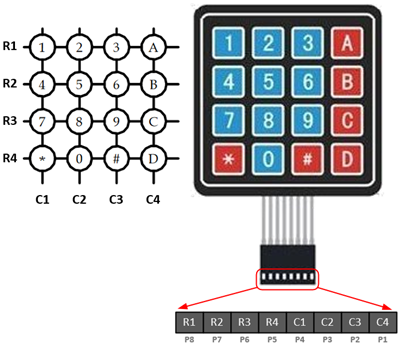
Connection Diagram
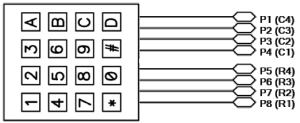
Keypad Connection for Open-Drain Output Pins
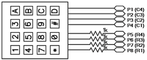
Keypad Connection with Resistors for Regular Output Pins