Keyes KY-040 Rotary Encoder
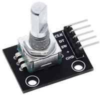
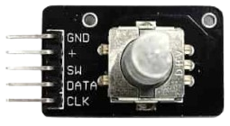
The Keyes KY-040 is a commonly used incremental rotary encoder module in embedded systems. It provides precise control over rotational input, making it ideal for volume adjustments, menu navigation, and motor control applications.
Key Features:
- Type: Incremental Rotary Encoder
- Rotation: The KY-040 allows unlimited 360° continuous rotation without mechanical stops.
- Steps per Revolution (Detents): It has 20 steps (detents) per full 360° rotation. Each detent represents an 18° rotation (360° / 20 detents).
- Push-Button Switch: Pressing the knob activates an integrated push-button, adding an extra input method. Active LOW (button press pulls the pin LOW)
- Dual Output Channels (CLK and DT): These channels provide quadrature output (2-bit gray code), enabling the determination of rotation direction and speed.
- Operating Voltage: 5V DC (typically works with 3.3V as well)
- Interface: Digital quadrature output for position and direction detection
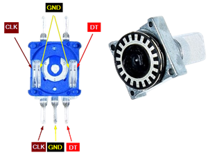
- Pinout: The KY-040 module has five pins:
- GND: Ground connection.
- VCC (+): Power supply input, typically 5V.
- SW: Output from the integrated push-button switch; active low.
- DT (Data): Output channel B.
- CLK (Clock): Output channel A.
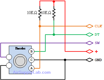
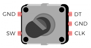
Working Principle:
Inside the KY-040, a metal ring with small tabs is attached to the knob. As you rotate the knob, the metal ring also rotates, and the tabs intermittently make and break contact with the internal contacts. This action generates two pulse signals, one on each output channel (CLK and DT), which are slightly out of phase.
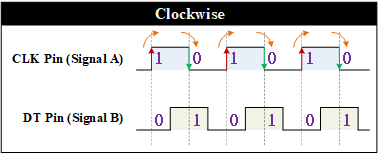
The CLK (Clock) and DT (Data) pins emit square wave pulses due to the physical contact of the tabs on the metal ring with the internal contacts. The phase difference between these pulses determines the direction of rotation:
- Clockwise Rotation: When turning clockwise, the CLK pulse leads to the DT pulse.
- Counter-Clockwise Rotation: When turning counter-clockwise, the DT pulse leads to the CLK pulse.
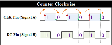
Each detent (a noticeable click or stop as the knob rotates) corresponds to one complete pulse cycle on both channels, which allows the microcontroller to count steps and determine the rotation's direction.
Application Notes
- Pull-Up Resistors: Some setups may require pull-up resistors on the CLK, DT, and SW pins to ensure stable readings.
- Debouncing: Mechanical contacts may cause bouncing, so software debouncing or low-pass filtering may benefit stability.