Pulse-Width Modulation (PWM)
Pulse-Width Modulation — What is it?
A good definition of Pulse-Width Modulation (PWM) is already in the name itself. It means modulating/varying the width of the pulse only, not the frequency. In the digital control system, PWM is used to control the amount of power sent to a device. Therefore, the PWM is a very effective technique for controlling analog devices using the digital outputs of a microcontroller. It is widely used in many fields, such as measurement, communication, power control, and transformation.
Principle
A PWM signal consists of two main components that define its behavior: a duty cycle and a frequency.
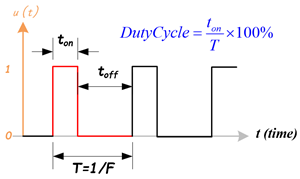
- Duty Cycle
The duty cycle describes the amount of time the signal is in a high (on) state as a percentage of the total time it takes to complete one cycle. A lower duty cycle corresponds to lower power because the power is off most of the time. The duty cycle is expressed percent, 100% duty cycle would be fully on as same as setting the signal to Vcc (high); 0% duty cycle would be the same as grounding the signal. - Frequency
The frequency determines how fast the PWM completes a cycle, ie. 100Hz would be 100 cycles per second. In other words, it shows how fast the PWM switches between high and low states.
In the digital system, PWM is the method to produce variable voltage using digital means. Typically, a digital system only has two output voltages, the high (5V, 3.3V … etc.) or the low (0V). But, how it is possible that a digital system can produce a voltage that is between the high and low voltages? Here, we use mathematics to analyze the PWM signal and the average output.
Mathematical Analysis of PWM signal
PWM uses a rectangular pulse wave whose pulse width is modulated resulting in the variation of the average value of the waveform. Consider a waveform such as shown in figure 2.
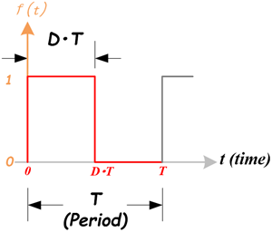 Figure 2: A Pulse Wave
The pulse signal is f(t) with period T and a duty cycle D (0.0~1.0). The average voltage of the waveform is given by:
$\bar y = \frac{1}{T}\int_0^T {f(t)dt} $
Just focus on one cycle T, as f(t) is a pulse wave, its positive-pulse is for 0 < t < D×T, and zero-pulse is for D×T < t < T. The above expression then becomes:
$\begin{array}{l} \bar y = \frac{1}{T}\left( {\int_0^{DT} {1\;dt} + \int_{DT}^T {0\;dt} } \right)\\ \quad = \frac{1}{T}\left[ {DT \times 1 + T(1 - D) \times 0} \right]\\ \quad = D \end{array}$
From this, it is obvious that the average value of the signal is directly dependent on the duty cycle D.
For example, if a digital signal produces a pulse high (5V) and a low (0V) equally, let us assume the signal in the high state for 1 microsecond and in a low state for 1 microsecond. The duty cycle is 50%, so the average voltage would be 2.5 volts. Now, change the high voltage in a high state for 7 microseconds and in a low state for 3 microseconds. The duty cycle now becomes to 70%, the average voltage would measure 70% of 5 volts or 5v x 0.7 = 3.5 volts.
Types of PWM
There are a couple of types of PWM, and they can be classified in different ways.
Classify PWM Signal by Methods: Symmetric and Asymmetric
There are two kinds of PWM signals: Symmetric and Asymmetric.
- Symmetric PWM:
- The pulses of asymmetric PWM signals are always symmetric with respect to the center of each PWM period.
- Symmetric PWM is often used for three-phase AC induction and brushless DC motors, due to the lower harmonic distortion that is generated on phase currents in comparison to asymmetric PWM methods.
- Asymmetric PWM:
- The pulses of an asymmetric PWM signal always have the same side aligned with one end of each PWM period.
- Asymmetric PWM can be used for stepper motors and other variable-reluctance motors.
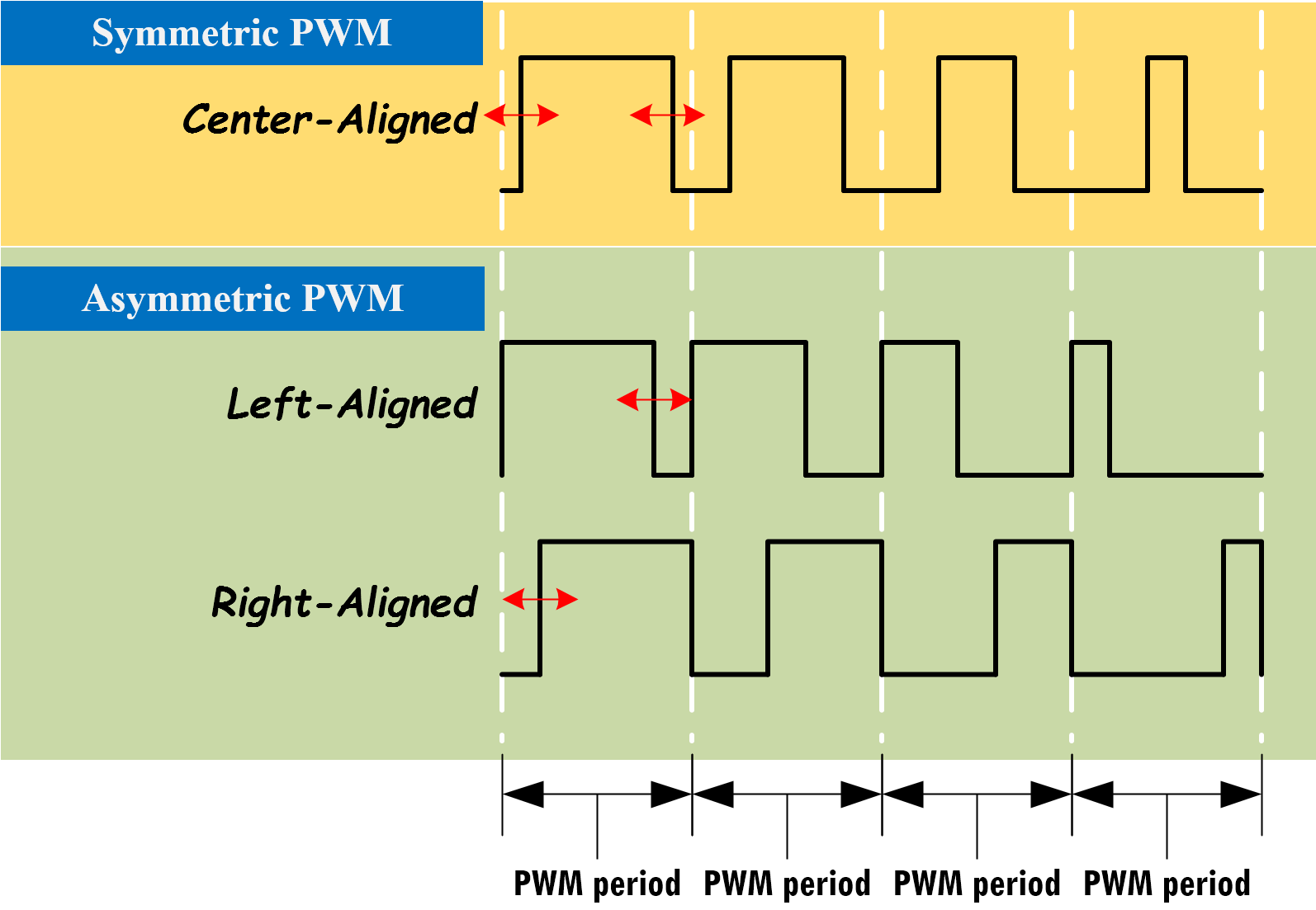
Figure 3: Three Types of PWM Signal: Center-Aligned, Left-Aligned, and Right-Aligned PWMs
Classify PWM Signal by Signal-Alignment
The PWM signal can be classified by signal alignment in four different types:
- Center-aligned PWM:
- Symmetric PWM
- Center-aligned PWMs are most often used in AC motor control to maintain phase alignment
- Left-aligned PWM
- Asymmetric PWM
- Left-aligned PWMs are used for most general-purpose PWM uses
- Right-aligned PWM
- Asymmetric PWM
- Right-aligned PWMs are typically only used in special cases that require alignment opposite of left-aligned PWMs
- Dual-edge PWM
- Dual-edged PWMs are optimized for power conversion where phase alignment must be adjusted
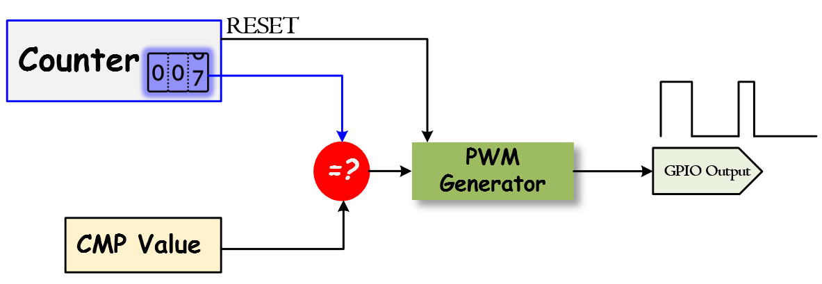
Generating PWM with Microcontroller using Timer/Counter
The basic idea to generate a PWM signal is to use a counter (or timer), a CMP (compare) value, and a digital output pin. The counter continuously counts up or down and is compared with the CMP value. The digital output (PWM) will be changed when the counter matches the CMP value, or when the counter resets. It can be implemented by software or hardware. Most microcontrollers already have hardware modules that can generate PWM signals after initializing the registers.
PWM Timer
The PWM timer in the microcontroller runs in one of two modes: Count-Down mode or Count-Up/Down mode.
- In Count-Down mode, the timer counts from the Period (LOAD) value to zero, goes back to the Period (LOAD) value, and continues counting down.
- In Count-Up/Dow mode, the timer counts from zero up to the Period (LOAD) value, back down to zero, back up to the Period (LOAD) value, and so on.
Generally, the Count-Down mode is used for generating left- or right-aligned PWM signals, while the Count-Up/Down mode is used for generating center-aligned PWM signals.
Check the microcontroller's datasheet about the PWM timer. Most of the ARM microcontrollers use Count-Down mode.
Center-Aligned PWM
Center-Aligned PWM
A center-aligned PWM implements the PWM differently from all of the other modes. The PWM timer is configured in counting-up and -down mode. The counter starts at zero and counts up to the Period (LOAD) value, and when the Period (LOAD) value is reached, the counter starts counting back down to zero. In this mode, the Period (LOAD) value is actually half of the period of the final PWM output.
- A single compare (CMP) value, which contains the duty cycle value, is constantly compared with the PWM timer (COUNTER) value. When the timer (COUNTER) value is less than the CMP value, the PWM output signal is de-asserted.
- When the timer (COUNTER) value exceeds or is equal to the CMP value, the PWM output signal is asserted. When the timer (COUNTER) value reaches the Period (LOAD) value, the timer starts counting down to zero.
- When the timer (COUNTER) value is less than or equal to the CMP value, the PWM output signal is de-asserted, and the process repeats.
Left-Aligned PWM
Left-Aligned PWM
To create the Left-Aligned PWM, a PWM timer counts down from a specified maximum value, called Period (LOAD) value, to zero. When the timer counts to zero, the Period (LOAD) value will be reloaded to the timer and continue to count down.
- When the timer (COUNTER) value is greater than the CMP value, the PWM output signal is asserted.
- When the timer (COUNTER) value is less than or equal to the CMP value, the PWM output signal is de-asserted.
- When the timer counts to zero, the timer will reload the value from the Period (LOAD) value.
Right-Aligned PWM
Right-Aligned PWM
To create the Right-Aligned PWM, the PWM timer still runs on counting-down mode
- When the timer (COUNTER) value is greater than the CMP value, the PWM output signal is de-asserted.
- When the timer (COUNTER) value is less than or equal to the CMP value, the PWM output signal is asserted.
- When the timer counts to zero, the timer will reload the value from the Period (LOAD) value, and the process repeats.
Dual-Edge PWM
Dual-Edge PWM
A dual-edge PWM uses two different aligned PWM, one is right-aligned and another is left-aligned. Those two PWMs are connected to an AND gate, the output is the dual-edge PWM signal.