Inter-Integrated Circuit Bus (I2C Bus)
![]()
I2C (Inter-Integrated Circuit), pronounced I-squared-C, is also called IIC (pronounced I-I-C), or I2C (pronounced I-two-C). Philips designed the I2C in the early '80s, and It is typically used for lower-speed communication between peripheral devices and microcontrollers in short-distance. For example, EEPROM, ADC, RTC, etc.
I2C is a multi-master and multi-slave serial communication protocol, which means we can attach multiple ICs at a time with the same bus. In the I2C protocol, communication is always started by the master; in the case of a multi-master, only one master has ownership of the bus.
I2C Physical Layer
I2C is a two-wire communication protocol. It uses only two wires for communication. One wire is used for the data (SDA), and the other is for the clock (SCL). In I2C, both buses are bidirectional, which means the master can send and receive the data from the slave. The masters control the clock bus, but in some situations, slave devices may force the clock low at times to delay the master sending more data or to require more time to prepare data before the master attempts to clock it out. This is called "Clock stretching" and is described in the protocol section.
All slaves and masters are connected with the same data and clock bus. The important thing is to remember these buses are connected using the WIRE-AND configuration, which is done by putting both pins as "open drain". An open drain means that the device can pull the corresponding signal line low but cannot drive it high. Thus, the open-drain configuration allows I2C to connect multiple nodes to the bus without any short circuits from signal contention.
In other words, the open drain allows the master and slave to drive the line low and "release" to a high impedance state. When the master and slave release the bus, they need a pull-up resistor to pull the line high. Each signal line has a pull-up resistor to restore the signal to high when no device is asserting it low. The value of the pull-up resistor is very important from the perspective of the design of the I2C system because the incorrect value of the pull-up resistor can lead to signal loss. But a good rule of thumb is to start with 4.7 KΩ and adjust down if necessary.
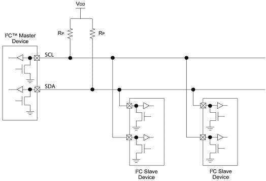
Figure 1: Basic Internal Structure of the Slave and Master Devices
Figure 1 shows a simplified view of the internal structure of the slave and master devices on the SDA/SCL lines, consisting of a buffer to read input data and a pull-down FET to transmit the data. A device can only pull the bus line low (provide short to ground) or release the bus line (high impedance to ground) and allow the external pull-up resistor to raise the voltage. This is important when dealing with I2C devices since no device may hold the bus high. This property is what allows bidirectional communication to take place.
I2C is a fairly robust protocol and can be used with short wire runs (2 ~ 3 m). Smaller resistors are better for long runs or systems with many devices.
Wired Connection
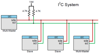
The above diagram shows a simplified equivalent circuit for an I2C connection between the masters and slaves. All I2C master and slave devices are connected with only two wires: serial data (SDA) and serial clock (SCL). Each device can be a transmitter, a receiver, or both. Some devices are masters – they generate bus clocks and initiate communication on the bus; other devices are slaves and respond to the commands on the bus. To communicate with a specific device, each slave device must have a unique address on the bus. I2C master devices (usually microcontrollers) don't need an address since no other (slave) device sends commands to the master.
We know that the I2C communication protocol supports multiple masters and multiple slaves, but most system designs include only one master.
Bus Signals
The I2C uses two signals: SDA and SCL. Both signals are bidirectional and connected via resistors to a positive power supply voltage. All the devices on the bus must use open-collector or open-drain pins. Therefore, when the bus is free, both signals are logic high. Activating the signal means pulling it down (wired AND) to logic 0. The number of devices on a single I2C bus is almost unlimited — the only requirement is that the bus capacitance does not exceed 400 pF.
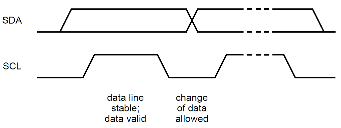
Signal Timing
The I2C is a serial synchronous communication protocol. Each clock transfers one bit of data. The SDA signal can only be changed when the SCL signal is low; the data should be stable when the clock is high.
I2C Data Transfer Protocol
Data on the I2C bus is transferred in 8 bits. There is no limitation on the number of bytes; however, each byte must be followed by an acknowledge (ACK) bit. This bit signals whether the device is ready for the next byte. For all data bits, including the ACKnowledge bit, the master must generate clock pulses. If the slave device does not acknowledge the transfer, there is no more data, or the device is not ready for the transfer yet. The master device must either generate a STOP or REpeated START condition bit.
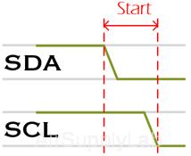
START CONDITION
The default state of the SDA and SCL lines is high. A master issuing the Start condition first pulls the SDA line low and then pulls the SCL line low. This puts all slave devices on notice that a transmission is about to start. The I2C bus is considered busy after the assertion of the START bit. If two master devices wish to take ownership of the bus at once, whichever device pulls SDA low first wins the race and gains control of the bus.
STOP CONDITION
Once all the data frames have been sent, the master will generate a stop condition. The bus master first releases the SCL and then the SDA line. The I2C bus is considered free after the assertion of the STOP bit.
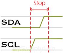
A Stop condition ALWAYS denotes the END of a transmission. Even if it is issued in the middle of a transaction or in the middle of a byte. It is "good behavior" for a master that, in this case, it disregards the information sent and resumes the "listening state", waiting for a new start condition.
REPEATED START
The repeated start condition is similar to the START condition, but both are different. The repeated start is asserted by the master before the stop condition (When the bus is not in an idle state).
A Repeated Start condition is asserted by the master when the bus master does not want to lose control of the bus. The repeated start is beneficial for the master when it wants to start a new communication without asserting the stop condition.
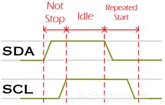
The repeated start is beneficial when more than one master is connected with the I2c Bus.
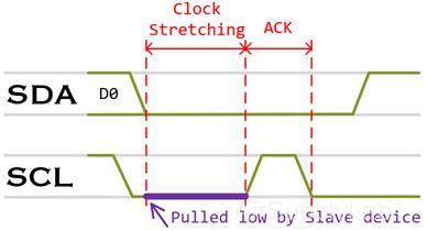
CLOCK STRETCHING
Sometimes, the master data rate will exceed the slave's ability to provide data. The slave is not ready to send the data; for example, the A/D conversion has not been completed, or the previous operation has not been completed.
In this case, the slave device will execute what is referred to as "clock stretching". Typically, all clocks are driven by the bus master. The slave places the data on the bus or fetches data off the bus in response to the master's clock pulse. During the data transfer processing, the addressed slave can pull the SCL line low to pause the transaction. After processing the received data, the slave will release the SCL line high to resume communication.
The clock stretching is how slaves drive the SCL line, but it is a fact that most of the slaves do not drive the SCL line.
In the I2C communication protocol, most I2C slave devices do not use the clock stretching feature, but every master should support the clock stretching.
Arbitration in I2C
Arbitration is required in the multi-master case, where more than one master tries to communicate with a slave simultaneously. In I2C, arbitration is achieved through the SDA line.
For example, if two masters in the I2C bus try to communicate with a slave simultaneously, then they will assert a START condition on the bus. The SCL clock line would be already synchronized by the wired and logic.
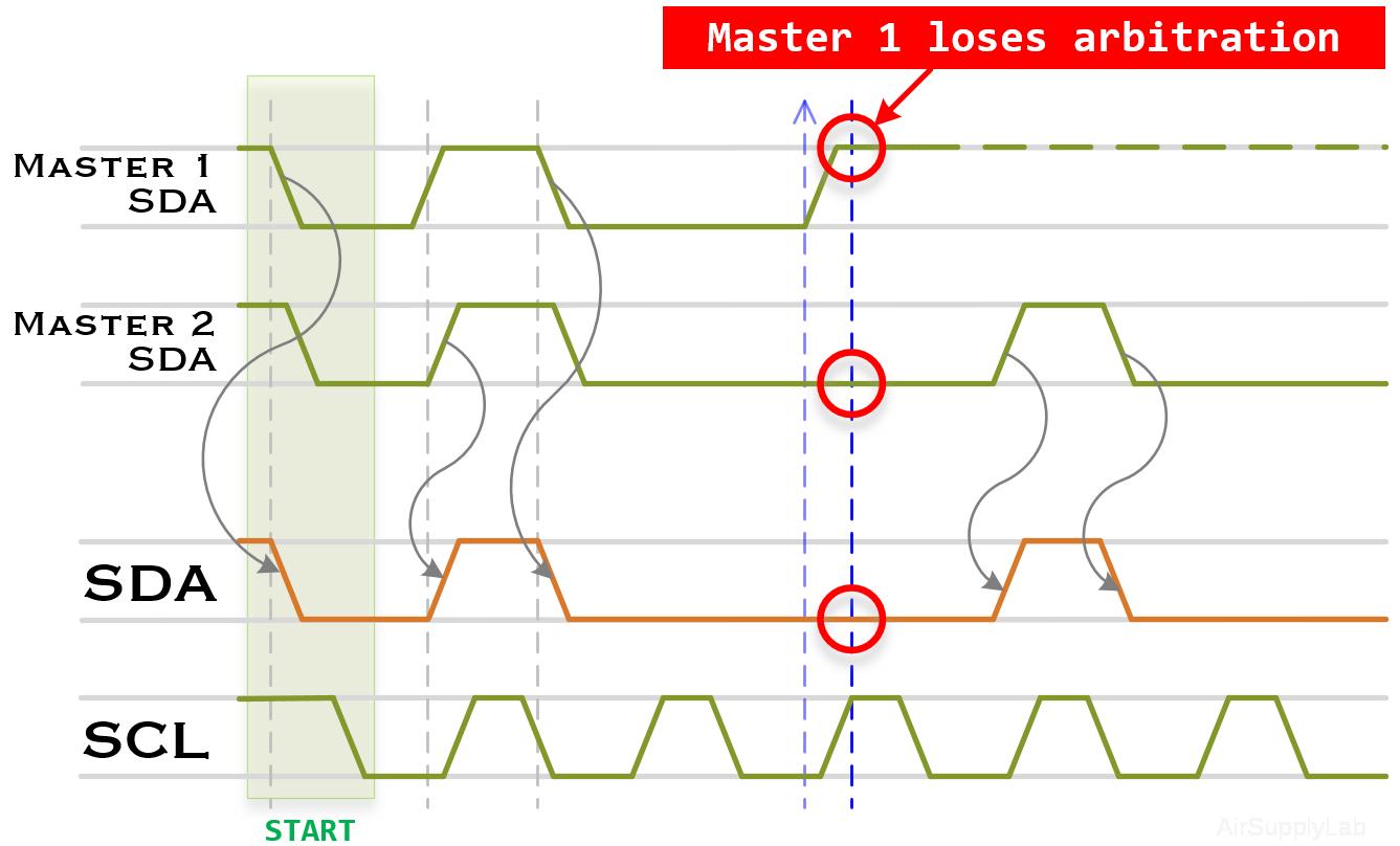
In the above case, everything will be good till the state of the SDA line is the same as what is the masters driving on the bus. If any master sees that the state of the SDA line differs, what drives it? Then, they will exit from the communication and lose their arbitration.
The master losing their arbitration will wait until the bus becomes free.
Handshaking Process in I2C Protocol
Communication with 7-bit I2C Slave Address
Each slave device on the I2C bus should have a unique 7-bit address, called a slave address. The master device generates all the serial clock pulses and the START and STOP conditions bit. Data is transferred with the most significant bit (MSb) first.
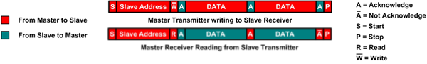
Data transfer from a master transmitter to a slave receiver (data write mode)
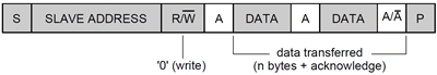
- Before transmitting, the master needs to detect the bus status. If the bus is not busy, this means both data and clock lines remain high, and then the master sends a START condition bit.
- The first byte transmitted by the master is the 7-bit address of the slave (it wishes to communicate with) and is followed by a direction bit representing whether it wishes to write (0) to or read (1) from the slave.
- If the slave exists on the bus, it will respond with an ACK bit (active low for acknowledgment) for that address.
- When the master receives the ACK bit, it will transmit the following data on the bus and wait for the ACK signal from the slave. Continue this step until all the data are transmitted.
- The master ends transmission with a STOP bit.
Data transfer from a slave transmitter to a master receiver (data read mode)
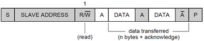
- Before transmitting, the master needs to detect the bus status. If the bus is not busy, data and clock lines remain high, and the master sends a START condition bit.
- The master transmits the first byte (salve address with a read bit).
- The slave returns an ACK bit, and the first data byte is transmitted to the master.
- The master returns an ACK bit; the slave sends the following data on the bus. The master sends an ACK bit after every byte except the last one.
- When the master receives the last data byte, an NAC (not acknowledged) bit will be sent to the slave.
- The master ends transmission with a STOP bit.
Combined Mode
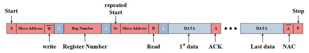
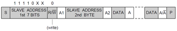
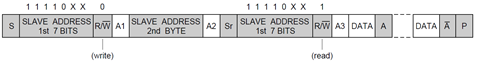
Sometimes, the master must write some data and then read it from the slave device. In such cases, it must first write to the slave device, change the data transfer direction, and then read from it. This means sending the I2C address with the R/W bit set to write and then sending additional data like the registered address. After the writing, the master device generates the REpeated START (RESTART) condition and sends the I2C address with the R/W bit set to read. After this, the data transfer direction changes, and the master device reads the data.
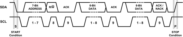
7-bit I2C Slave Address
Two slave addressing formats are defined in the I2C specification: 7-bit and 10-bit addressing. Standard Mode I2C makes use of 7-bit addressing. 10-bit addressing was later added as an extension to standard mode I2C.
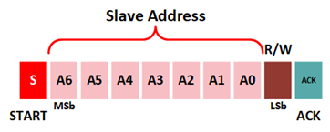
In the 7-bit addressing format, the slave address is transferred in the first byte after the START condition bit. The bit[7:1] of the byte comprises the slave address, followed by a direction bit at bit[0]. The format is shown in the following diagram.
A seven-bit wide address space theoretically allows 128 I2C addresses – however, some addresses are reserved for special purposes. Thus, only 112 addresses are available with the 7-bit address format.
Reserved address in 7-bit address space
Two groups of addresses are reserved for special functions:
- 000 0XXX
- 111 1XXX
The following table shows I2C addresses reserved for special purposes:
| Slave Address | R/W bit | Description | |
| 1 | 000 0000 | 0 | General call address |
| 2 | 000 0000 | 1 | START byte |
| 3 | 000 0001 | X | CBUS address |
| 4 | 000 0010 | X | Reserved for different bus format |
| 5 | 000 0011 | X | Reserved for future purposes |
| 6 | 000 01XX | X | Hi-Speed Master code |
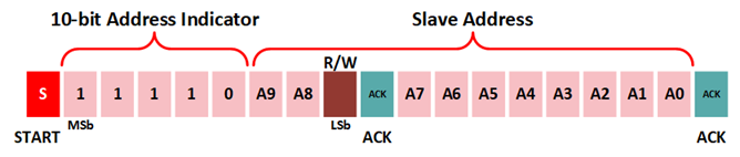
| 7 | 111 10XX | X | 10-bit slave addressing format |
| 8 | 111 11XX | 1 | Device ID |
10-bit I2C Slave Address
10-bit addressing expands the number of possible addresses. Devices with 7-bit and 10-bit addresses can be connected to the same I2C bus, and both 7-bit and 10-bit addresses can be used in all bus speed modes. Currently, 10-bit addressing is not being widely used.
Feature of I2C Bus
- Synchronous communication using two bidirectional open-drain lines pulled up with resistors
- Serial Data Line (SDA)
- Serial Click Line (SCL)
- Typical voltages used: +5 V or +3.3 V
- It can be designed as
- a single master and multiple slaves
- multiple masters
- a combination of masters and slaves
- Each device connected to the I2C bus is software-addressable by a unique address
- Bus speed supported:
- Low-speed mode: 10 Kbps
- Standard-mode: 100 Kbps
- Fast-mode: 400 Kbps
- Fast-mode Plus: 1 Mbps
- High-speed Mode: 3.4 Mbps
I2C Q&A
Q1: A master begins communication by transmitting a single start bit. How can the slave(s) devices differentiate between a start and data bits?
A1: A start bit is generated by changing the state of the data line (SDA) from high to low while the clock line (SCL) is high. In contrast, transitions between two data states, for example, from 1 (high) to 0 (low), will only occur when the clock line (SCL) is low.
Q2: How does the I2C interface protocol define packet transmission stop?
A2: A stop bit is generated by changing the state of the data line (SDA) from low to high, again only while the clock line (SCL) is high.
Q3: How does the I2C interface protocol define a bit of data (1 or 0)?
A3: A bit of data is defined by a clock pulse. The data line must be stable during this period of time.
Q4: How many bits comprise a data packet?
A4: 9bit (8-bit for data + 1-bit ACK/NAK)
Q5: How many slaves can be addressed by a master?
A5: The slave address (SLA) is 7-bit wide, suggesting up to 27 slaves. However, the address is reserved, so in practice, only 127 slaves may be addressed.
Q6: What is the bit ordering for transmitting an address and data?
A6: Most significant bit (MSB) first.
Q7: What is the difference between a packet and a session?
A7: A single session is defined by the master sending an address (SLA-R/W) packet and reading or writing one or more data packets.
Q8: Once a slave decodes the 7 address bits and determines the master is talking to it, how does the slave know if the master will read data from the slave or Write data to the slave?
A8: After the 7 address bits, the master will transmit a read bit (SLA+R) or a write bit (SLA+W).
Q9: Once a slave decodes the 7 address bits and learns the direction of communications (SLA+R/W), it acknowledges (ACK) that it is ready by setting the data line (SDA) to zero. This is the 9th bit in the address packet. How can the slave bring this line low without generating contention on the SDA line? In other words, how can both the master and a slave use the same line to both send and receive data?
A9: Each of the two wires (SDA and SCL) includes a pull-up resistor. A slave device writing to SDA only needs to pull the line low for each 『0』written; otherwise, it leaves the line alone to write a 『1』, which occurs due to the lines being pulled high externally by the pull-up resistor. This is commonly known as a wired-AND configuration. Here is a link to learn more about wired-AND and wired-OR configurations.
Q10: When the slave sends data to the master (SLA-R), the slave controls the data line (SDA); who generates the clock pulse?
A10: The master always generates the clock pulse.
Q11: If the master always generates the clock pulse, why does the clock line (SCL) use an open-collector output configuration, allowing multiple devices to share this bus line?
A11: The I2C interface protocol allows multiple masters.
References: