Lesson 12: Run Simulation on ModelSim (Pre-Simulation)
The ModelSim-Intel FPGA edition software is a version of the ModelSim software targeted for Intel FPGA devices. The software supports Intel gate-level libraries and includes behavioral simulation, HDL test benches, and Tcl scripting.
There are two editions of ModelSim-Intel FPGA software: ModelSim-Intel FPGA edition and ModelSim-Intel FPGA Starter edition.
- Recommended for simulating all Intel FPGA designs (Intel Arria FPGA, Intel Cyclone FPGA, and Intel Stratix FPGA designs, and Intel MAX CPLDs)
- 33 percent faster simulation performance than ModelSim-Intel FPGA starter edition software
- No line limitations
- Software license required
- Mixed language support
- Support for simulating small Intel FPGA designs
- 10,000 executable line limitations
- Free no license required
- Mixed language support
- ModelSim-Intel FPGA starter edition's simulation performance is lower than ModelSim-Intel FPGA editions.
- ModelSim-Intel FPGA starter edition has a line limit of 10,000 executable lines compared to the unlimited number of lines allowed in the ModelSim-Intel FPGA edition software.
In this session, you will learn how to use ModelSim to simulate the Verilog code.
13.1. Create a New Project
Create a New Project
- Create a new folder for this exercise at "<the folder you created for this lab>/L05_ModelSim"
- Launch ModelSim-Intel Starter edition
On the left end of the taskbar, select the Start icon, or press the Windows logo key
  on the keyboard. and scroll to find the Intel FPGA xx.x.x.x Edition folder. Select on the folder and click on
  ModelSim-Intel FPGA Starter Edition icon to launch the software.
 - Create a new Project
- Select File ➤ New ➤ Project... from the menu bar.
This opens the Create Project dialog where you can enter a Project Name, Project Location, and Default Library Name (Figure 1) - Enter the project name, in this case, the project is called cmp4bit
- Click Browse... button for the Project Location field to select a folder where the project file will be stored. Change it to the folder you create in step 1.
- Leave the Default Library Name set to work.
- Click OK.
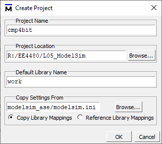
Figure 1: Create Project Dialog - Select File ➤ New ➤ Project... from the menu bar.
- You might be asked if you want to create the project directory, click the Yes button.
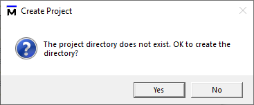
Figure 2: Create a new Directory - Once you click OK to accept the new project setting, a blank window and the Add items to the Project dialog will appear (Figure 3). While we can use this dialog to create new source files or add existing ones, we will not be using this option for the exercise. We will add source files later, so just click on the Close button.
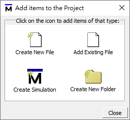
Figure 3: Adding New Items to a Project Dialog - You now have a project by name of cmp4bit.
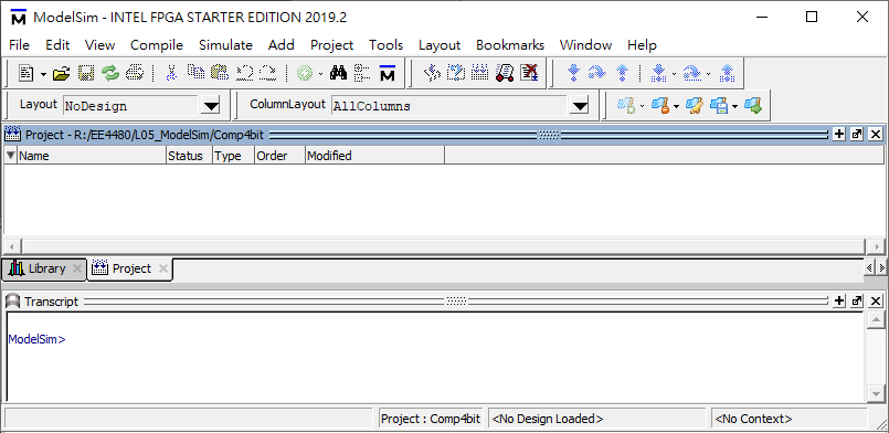
Figure 4: Main Window of ModelSim
13.2. Add New Verilog Files to the Project
Add New Verilog Files to the Project
Now we need to add a new file to the project.
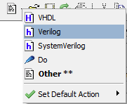
- Click on the menu File ➤ New ➤ Source ➤ Verilog, or click and hold on the
 button, then select the Verilog.
- Now you can edit the Verilog code in the edit area.
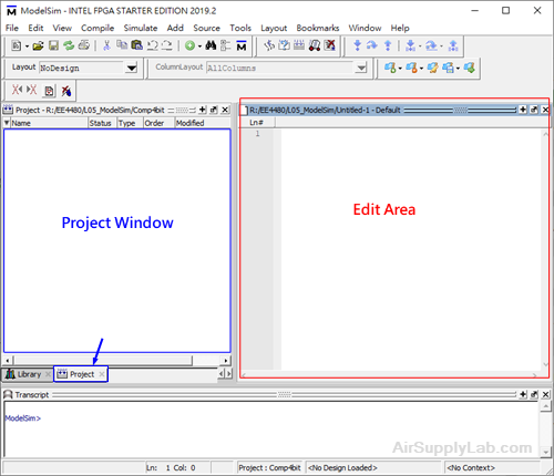
- Type the Verilog for a 4-bit comparator using behavioral modeling.
Then be sure to save the file to the comp_4bit.v file by clicking on File ➤ Save As...
The Verilog code for the 4-bit comparator.
//Save file to comp_4bit.v module comp_4bit(a, b, lg, eq, ls); input [3:0] a; input [3:0] b; output lg, eq, ls; reg lg, eq, ls; always @(*) begin lg = 1'b0; eq = 1'b0; ls = 1'b0; if (a > b) begin lg = 1'b1; end else if (a == b) begin eq = 1'b1; end else begin ls = 1'b1; end end endmodule - Click on the Project Window. Right-click and select Add to Project ➤ Existing File..., then select the file we just created for the project. In the project windows, you should see the file has been added to the project.
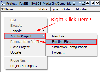
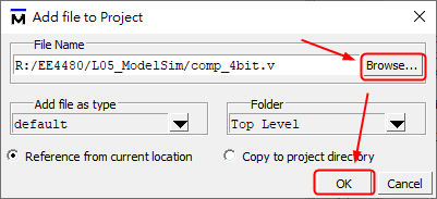
Figure 8: Add file to the Project Dialog - We also need to add a testbench to the project. Follow steps 7 ~ 10 again to add comp_4bit_tb.v to the project.
The Verilog code for the testbench is shown below.
//Save file to comp_4bit_tb.v `timescale 1ns/1ns module test(); reg [3:0] a; reg [3:0] b; wire lg, eq, ls; comp_4bit DUT (.a(a), .b(b), .lg(lg), .eq(eq), .ls(ls)); initial begin a = 4'd10; b = 4'd14; #5 a = 4'd3; b = 4'd12; #5 a = 4'd6; b = 4'd6; #5 $stop; end endmodule - You should now see two files listed in the Project window (Figure 9). Question mark icons in the Status column indicate that the file has not been compiled or that the source file has changed since the last successful compile. The other columns identify file type (e.g. Verilog or VHDL), compilation order, and modified data.

Figure 9: Newly Added Project Files Display a for Status
13.3. Compile the Design
Compile the Design
- Compile the files.
- Right-click in the Project window and select Compile ➤ Compile All from the pop-up menu.
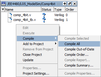
- ModelSim compiles both files and changes the symbol in the Status column to a green checkmark
 . A checkmark means the compile succeeded. If the compile fails, the symbol will be a red
  , and you will see an error message in the Transcript window.

- Right-click in the Project window and select Compile ➤ Compile All from the pop-up menu.
- View the design units.
- Click the Library tab.
- Click the
 icon next to the work library.
You should see two compiled design units, their types (modules in this case), and the path to the underlying source files.
Figure 12: Library Window with Expanded Library
13.4. Load the Design for Simulation
Load the Design for Simulation
After compiling the design, you can load the design into the simulation.
- Load the test module.
- In the Library window, click the
 icon next to the work library to show the files contained there.
 - Double-click test to load the design.

Figure 13: Verilog Modules Compiled into work Library
- In the Library window, click the
- You also can load the design by selecting Simulate ➤ Start Simulation in the menu bar. This opens the Start Simulation dialog. With the Design tab selected, click the
 sign next to the work library to see the comp_4bit and test modules. Select the test module and click OK.
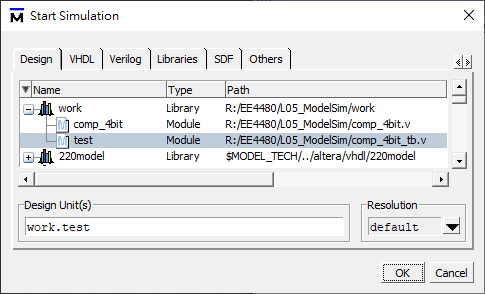
Figure 14: Loading Design with Start Simulation Dialog
Prepare Simulation
After loading the design into the simulator, but before a simulation can be started, you need to set up the simulation/debug environment for the design. That is, you need to open the debug windows you consider important and select signals and variables, ... which you want to trace on those debug windows.
A good choice in the beginning for debug windows include:
- Wave — See waveforms
- Objects — See signals and their values
- Source — Trace your code line-by-line
- Locals — See variables and their values
These windows can be opened from the main menu View.
Next, you need to tell the simulator which signals you want to trace in the Wave window.
You can add signals into the Wave window using one of the following methods:
- Select signals in Objects pane ( Shift + Left Key on the mouse) and drag-n-drop the selection to Wave panel.
- Right-click in Object window and select Add to Wave.
- Click Add ➤ To Wave ➤ Selected Signals from the main menu.
Now, everything should look something like below:
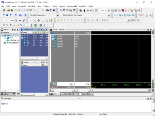
Figure 15: ModelSim Main Window Showing Workspace, Object, Locals and Source Windows
It is very beneficial to save the current signal configuration of the wave window by selecting File ➤ Save.
13.5. Run Simulation
Run Simulation
You can simulate the design.
- Enter 5 ns as the length of time we would like to simulate for in the Run Length box and click the
 Run icon as shown below:
- You can click the Run icon again to continue the simulation for the next 5 ns, or click
 Run-All icon to run all testbench code until $stop or $finish instruction in the testbench code.
Now run the simulation for a few hundred nanoseconds. You should see how each signal takes at startup their initial values and how inputs and outputs change after a few clock cycles. The Waveform window should look something like below:
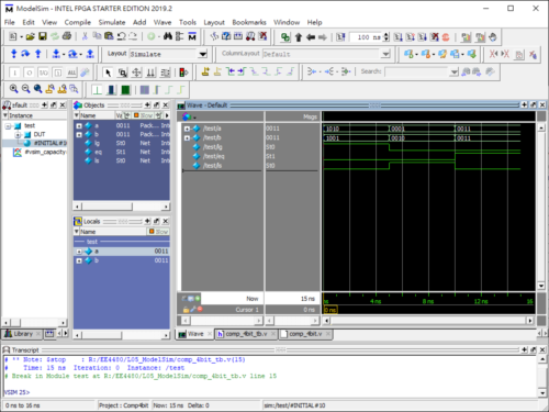
Figure 17: Results for the Simulation
13.6. Lesson Wrap-Up
Lesson Wrap-Up
This concludes this lesson. Before continuing you need to end the current simulation and close the current project.
- Select Simulate ➤ End Simulation. Click Yes.
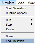
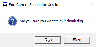
Figure 18: End Simulation - In the Project window, right-click and select Close Project.
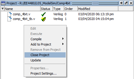
Figure 19: Close Project
If you do not close the project, it will open automatically the next time you start ModelSim.
Q&A