Lesson 11: System Clock Setting
Every microcontroller needs clock signals. Clock signals are connected to all the components inside of a microcontroller, such as CPU, memory systems, digital and analog peripherals. They govern the speed at which the processor executes instructions, the data transfer rate of serial communication signals, the speed of the timer, the synchronous signal for parallel communication protocols, and so much more.
The clock source comes in the form of an oscillator. Most microcontrollers have internal oscillators and optional connections for external crystal oscillators.
- Internal Oscillators are typically R-C oscillators. R-C oscillators are easy to implement, but they are not precise and can be affected by temperature, noise, and voltage. Usually, the internal oscillators are used for producing lower frequencies.
- External Oscillators provide a more accurate, stable, and fixed frequency at the output. If you need an external oscillator, you need to make sure that your oscillator can be supported by the microcontroller by checking the microcontroller's datasheet.
Most microcontrollers have Phase-Lock-Loop (PLL) circuits to provide different clock frequencies that can be adjusted by software.
EK-TM4C123GXL LaunchPad
Clock System
There are multiple clock sources for use in the TI TM4C123GXL Tiva C LaunchPad. Some of these sources are external while most clock sources are internal.
- Main Oscillator (MOSC)
- Primary external source.
- Can be used to drive the internal 400 MHz PLL.
- TI TM4C123GXL Tiva C LaunchPad comes with a 16 MHz onboard crystal connected to MOSC.
- Needed to clock the 480 MHz USB PLL unit.
- Precision Internal Oscillator (PIOSC)
- This oscillator is an on-chip 16 MHz with 1% accuracy and 3% accuracy over temperature that is the clock source the microcontroller uses during and following POR (Power-on Reset).
- Can be used to drive the internal 400 MHz PLL.
- Can clock internal peripherals like ADC blocks, ...
- Low-Frequecncy Internal Oscillator (LFIOSC)
- Typical clock frequency 30 KHz with 50% accuracy.
- This oscillator is intended for use during Deep-Sleep power-saving modes.
- Can be used when either or both MOSC and PIOSC are powered down.
- Not suitable for accurate time-based operations.
- Hibernation Module Clock Source
- This oscillator is intended to provide the system with a real-time clock source and may also provide an accurate source of deep sleep or Hibernate mode power saving.
- TI TM4C123GXL Tiva C LaunchPad comes with a 32.768 KHz onboard RTC crystal.
- This oscillator can be used for the system clock.
All of the aforementioned sources can be system clock sources. PIOSC should never be disabled unless needed and that is because if MOSC is used and it fails for some reason, PIOSC will take over the role of providing a clock signal.
400 MHz Phase-Lock-Loop (PLL)
TM4C123 comes with an internal 400 MHz PLL that can generate clock frequencies from 3.12 MHz to 80 MHz. It can be driven by two sources only:
- Precision Internet Oscillator (PIOSC)
- Main Oscillator (MOSC)
After power-on-reset, the default system clock frequency is 16 MHz.
The 80 MHz is the top operating clock speed for the TM4C123x microcontroller.
Registers
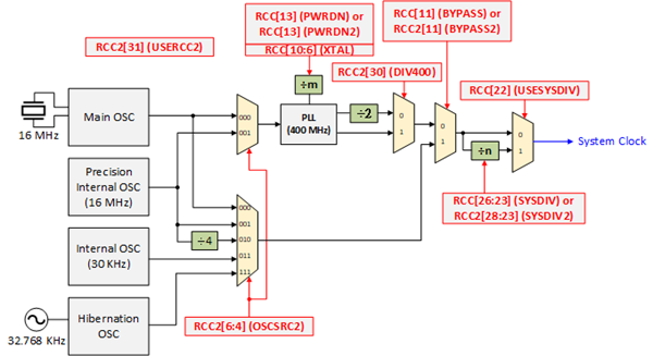
The PLL is configured using direct register writes to the RCC/RCC2 register. If the RCC2 register is being used, the USERCC2 bit must be set, and the appropriate RCC2 bit/field is used. The steps required to successfully change the PLL-based system clock are as following lists:
- Enable USERCC2 bit (RCC2[31]) to use RCC2 register field override the RCC register fields
- Bypass PLL while initializing. Enable BYPASS2 bit (RCC2[11]) to bypass the PLL output
- Set external crystal value XTAL (RCC[10:6]), and oscillator source OSCSRC2 (RCC2[6:4]) for PLL
- Clearing PWRDN2 (RCC2[13]) to active PLL
- Set Divide PLL DIV400 (RCC2[30]). DIV400=0: 200 MHz; DIV400=1: 400 MHz
- Set system clock divisor.
DIV400=0 Using SYSDIV2 (RCC2[28:23]) field as divisor
DIV400=1 Using SYSDIV2 and SYSDIV2LSB field (RCC2[28:22]) as a 7-bit divisor - Wait for the PLL to lock by polling the PLLLRIS bit in the Raw Interrupt Status (RIS[]) register
- Set BYPASS2 (RCC2[11]) to 0, select PLL as the source of the system clock
Sample Firmware Code in Keil C
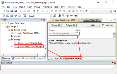
In Keil C, when you create a new project with the Startup package, the system_TM4C123.c will be added to your project. In the system_TM4C123.c code, the system clock frequency will be configured to 50MHz in the SystemInit() function by default.
There are two methods to disable the clock configuration in Keil C.
- You can check the source code in system_TM4C123.c at lin 26 ~ 36.
//--------------------- Clock Configuration ----------------------------------
//
//  <e> Clock Configuration
//          <i> Uncheck this box to skip the clock configuration.
//
// The following controls whether the system clock is configured in the
// SystemInit() function.  If it is defined to be 1 then the system clock
// will be configured according to the macros in the rest of this file.
// If it is defined to be 0, then the system clock configuration is bypassed.
//
#define CLOCK_SETUP 1
If the CLOCK_SETUP is defined as 0, the system clock configuration will be bypassed, and it will be default 16 MHz. - You can open the system_TM4C123.c file, and change it to the Configuration Wizard tab. Uncheck the Clock Configuration option to skip the clock configuration.

#include <stdio.h>
#include <stdlib.h>
#include <stdint.h>
#include <stdbool.h>

#include "TM4C123GH6PM.h"

void SetSystemClock_80MHz()
{
    // 1. Enable USERCC2 in RCC2
    SYSCTL->RCC2 |= 0x80000000; // RCC2[31]=USERCC2
    // 2. Bypass PLL while initializing
    SYSCTL->RCC2 |= 0x00000800; // RCC2[11]=BYPASS2
    // 3. Set external crystal value and oscillator source for PLL
    SYSCTL->RCC = (SYSCTL->RCC & ~0x000007C0) //Clear RCC[10:6]=XTAL
                  + (0x15 << 6);              // 16MHz extern xtal
    SYSCTL->RCC2 &= ~0x00000070;              // RCC2[6:4]=OSCSRC2 000=Main Oscillator
    // 4. Clearning PWRDN to active PLL
    // RCC2[13]=PWRDN 0:The PLL operate normally
    SYSCTL->RCC2 &= ~0x00002000;
    // 5. Set system clock
    // RCC2[30]=DIV400 Select 400MHz(from PLL)
    SYSCTL->RCC2 |= 0x40000000;
    //RCC2[28:21]=SYSDIV2 400MHz/(4+1) = 80MHz
    SYSCTL->RCC2 = (SYSCTL->RCC2 & ~0x1FC00000) + (0x04 << 22);
    // 6. Wait for PLL to lock by polling PLLLRIS
    while( (SYSCTL->RIS & 0x00000040) == 0) {};
    // 7. Set BYPASS to 0, select PLL as the source of system clock
    SYSCTL->RCC2 &= ~0x00000800;
}

int main()
{
    uint16_t  duty;
    SetSystemClock_80MHz();
    // Place your application code here

}
EK-TM4C1294XL LaunchPad
Clock System
There are multiple clock sources for use in the TI TM4C294XL Tiva C LaunchPad. Some of these sources are external while most clock sources are internal.
- Main Oscillator (MOSC)
- Primary external source.
- Can be used to drive the internal PLL.
- TI TM4C1294GXL Tiva C LaunchPad comes with a 25 MHz onboard crystal connected to MOSC.
- Needed to clock the 480 MHz USB PLL unit.
- Precision Internal Oscillator (PIOSC)
- This oscillator is an on-chip 16 MHz with 1% accuracy and 3% accuracy over temperature that is the clock source the microcontroller uses during and following POR (Power-on Reset).
- Can be used to drive the internal 480 MHz PLL.
- Can clock internal peripherals like ADC blocks, ...
- Low-Frequecncy Internal Oscillator (LFIOSC)
- Typical clock frequency 30 KHz with 50% accuracy.
- This oscillator is intended for use during Deep-Sleep power-saving modes.
- Can be used when either or both MOSC and PIOSC are powered down.
- Not suitable for accurate time-based operations.
- Hibernation Module RTC Clock Source
- This oscillator is intended to provide the system with a real-time clock source and may also provide an accurate source of deep sleep or Hibernate mode power saving.
- TI TM4C1294XL Tiva C LaunchPad comes with a 32.768 KHz onboard RTC crystal.
- This oscillator can be used for the system clock.
All of the aforementioned sources can be system clock sources. PIOSC should never be disabled unless needed and that is because if MOSC is used and it fails for some reason, PIOSC will take over the role of providing a clock signal.
After the power-on reset, the PIOSC acts as the system clock.
Phase-Lock-Loop (PLL)
TM4C1294 comes with an internal PLL that can generate clock frequencies up to 480 MHz. It can be driven by two sources only:
- Precision Internet Oscillator (PIOSC)
- Main Oscillator (MOSC)
After power-on-reset, the default system clock frequency is 16 MHz.
The 120 MHz is the top operating clock speed for the TM4C1294 microcontroller.
Registers
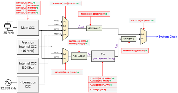
The following steps for initializing the system clock to use PLL from the main oscillator:
- Configure MOSC oscillator range to high-frequency range by setting 1 to SYSCTL_MOSCCTL[4] (OSCRNG) register, clear SYSCTL_MOSCCTL[2] (NOXTAL) register, and then clear SYSCTL_MOSCCTL[3] (PWRDN) to power on the main oscillator circuit.
- Waiting for oscillator ready by polling SYSCTL_RIS[8] (MOSCPUPRIS) register
- Configure PLL clock source to MOSC by setting SYSCTL_RSCLKCFG[27:24] (PLLSRC) to 0x03 (MOSC)
- Setup PLL M integer and fractional values to SYSCTL_PLLFREQ0[9:0] (MINT) and PLLFREQ0[19:10] (MFRAC), Q and N value to SYSCTL_PLLFREQ1[12:8] (Q) and SYSCTL_PLLFREQ1[4:0] (N), then enable the PLL power by setting SYSCTL_PLLFREQ0[23] (PLLPWR)
- Configure the memory timing parameter by SYSCTL_MEMTIM0 register
- Wait for PLL to lock by polling SYSCTL_PLLSTAT[0] (LOCK) register
- Enable MEMTIM update, new PLLFREQ accept, and USEPLL
Sample Firmware Code in Keil C
#include <stdio.h>
#include <stdlib.h>
#include <stdint.h>
#include <stdbool.h>

#include "TM4C1294NCPDT.h"

// fin  = fxtal / [(Q+1) * (N+1)]
//      = 25MHz / [(0+1) * (4+1)] = 5MHz
// fvoc = fin * MDIV
//      = 5MHz * 96.00 = 480MHz
// fsyclk = fvco / (PSYSDIV + 1)
//        = 480 / (3 + 1 ) = 120MHz
#define MINT    96
#define MFRAC   0
#define N       4
#define Q       0
#define PSYSDIV 3

#define FBCHT   0x6
#define EBCHT   0x6
#define FBCE    0
#define EBCE    0
#define FWS     0x5
#define EWS     0x5
#define MB1     0x00100010

void SetSystemClock_120MHz()
{
    // 1. Configure high-freq oscillator, power to main oscillator, and use external osiallator
    //    by setting SYSCTL_MOSCCTL register
    SYSCTL->MOSCCTL |= 1 << 4;          // high speed crystal connected to MOSC (>= 10 MHz)
    SYSCTL->MOSCCTL &= ~(1 << 2);       // enable external oscillator
    SYSCTL->MOSCCTL &= ~(1 << 3);       // power up the main oscillator

    // 2. Waiting for Oscillator ready by polling SYSCTL_RIS
    while(!(SYSCTL->RIS & (1 << 8))){}; // wait for oscillator ready

    // 3. Configure PLL clock source by SYSCTL_RSCLKCFG
    SYSCTL->RSCLKCFG &= ~(0xFF << 20);  // clear oscillator and PLL source field
    SYSCTL->RSCLKCFG |= (0x3 << 20);    // set MOSC as oscillator source
    SYSCTL->RSCLKCFG |= (0x3 << 24);    // set MOSC as PLL input source

    // 4. Setup PLL Freq and turn on the PLL power by SYSCTL_PLLFREQ0 and FREQ1
    SYSCTL->PLLFREQ0 = (MFRAC << 10) | MINT;    // set PLL M integer and fractional values
    SYSCTL->PLLFREQ1 = (Q << 8) | N;            // set PLL N and Q
    SYSCTL->PLLFREQ0 |= 1 << 23;                // power up the PLL

    // 5. Configure the memory timing parameter by SYSCTL->MEMTIM0
    // SYSCTL->MEMTIM0 = (EBCHT << 22) | (EBCE << 21) | (EWS << 16) | (FBCHT << 6) | (FBCE << 5) | FWS;      // set memory timing parameters
    SYSCTL->MEMTIM0 = (EBCHT << 22) | (EBCE << 21) | (EWS << 16) | (FBCHT << 6) | (FBCE << 5) | FWS; // set memory timing parameters
    SYSCTL->MEMTIM0 |= (1 << 4) | (1 << 20);

    // 6. Wait for PLL to lock by polling SYSCTL_PLLSTAT
    while( (SYSCTL->PLLSTAT & 0x01) != 0x01) {};

    // 7. Enable MEMTIM update, New PLLFREQ accept, and USEPLL
    SYSCTL->RSCLKCFG |= (1 << 31) | (1 << 30) | (1 << 28) | PSYSDIV;         // set PLL system clock divisor, lock the system clock to the PLL, and force a memory timing register update
}

int main()
{
    SetSystemClock_120MHz();
    // Place your application code here

}

