Lesson 03: Addressing Modes
The term Addressing Modes refers to the various ways a processor can specify instructions to access data. If the data number for instruction is in memory, the microprocessor will form a memory address to access it. If the data number is in a register inside the microprocessor, data accessing from memory is not needed. The addressing mode is associated more specifically with the operands, and a single instruction could exercise multiple addressing modes for each of the operands. There are various methods of giving source or destination addresses in instruction, thus there are various types of Addressing Modes. Here you will find the different types of Addressing Modes that are supported in the ARM Cortex-M microcontroller.
Immediate Addressing
A constant number can be put inside an instruction code. The address mode that places a constant data number inside the instruction is called immediate addressing. Immediate addressed instructions do not contain an address.
Syntax:
- 16-bit Thumb instructions: <instruction> {<cond>}{S} Rd, #imm8
- 32-bit ARM/Thumb-2 instructions: <instruction> {<cond>}{S} Rd, #imm16
- The # sign shows that the preceding term is constant data, not the address
- Immediate values are 16 bits (does not correspond to 255), so the range of valid immediate values is 0 through to 255 in decimal, or 0x00 through 0xFF in hexadecimal.

Example:
        MOV     R0, #25         ; Move the constant decimal value 25 to R0 register
        MOV     R1, #0x2F       ; Move the constant hexadecimal value 2Fh to R1 register
        MOV     R2, #2_1101     ; Move the constant binary value 00001101b to R0 register
        CMP     R0, #22
Register Addressing
Some instructions can operate on data inside the microprocessor registers. This is referred to as the Register Addressing Mode.
Immediate
Register with Immediate
Syntax:
- {label} <instruction> Rd, Rs, #imm

Example:
        ADD     R1, R2, #18     ; R1 <= R2 + 18
        AND     R0, R1, #0X0F   ; R0 <= R1 & 0x0F
        MUL     R0, R2, #8      ; R0 <= R2 * 8
Register
Register-to-Register:
Syntax:
- {label} <instruction> Rd, Rs {, Rm}


Example:
        ADD     R0, R1, R2      ; R0 <= R1 + R2
        ADD     R3, R4          ; R3 <= R3 + R4
        MOV     R1, R3          ; R1 <= R3
Scaled Register
Scaled Register-to-Register
Syntax:
- {label} <instruction> Rd, Rs, LSL <Rs | #imm> ; LSL: Logical Shift Left
- {label} <instruction> Rd, Rs, LSR <Rs | #imm> ; LSR: Logical Shift Right
- {label} <instruction> Rd, Rs, ASR <Rs | #imm> ; ASR: Arithmetic Shift Right
- {label} <instruction> Rd, Rs, ROR <Rs | #imm> ; ROR: Rotate Right
- {label} <instruction> Rd, Rs, RRX <Rs | #imm> ; RRX: Rotate Right with Extend
- {label} <instruction> Rd, Rs, Rm, <LSL|LSR|ASR|ROR|RRX> #imm ; LSL: Logical Shift Left


Example:
        MOV     R0, R1, LSL #3    ; R0 <= (R1 << 3)
        ADD     R0, R1, R2 LSR #2 ; R0 <= R1 + (R2 >> 2)
        MOV     R1, R3, ASR #7    ; R1 = R3 / 128, treats register value like is signed values (shifts in MSB)
        MOV     R2, R4, LSR #7    ; R2 = R4 / 128, treats register value like unsigned values (shifts in 0)
Indexed Addressing
ARM instructions do not support memory to memory data processing operations. Instead, they use special load and store instructions to move the data between the processor's internal registers and the memory. Therefore, all the values in the memory must be loaded into the registers before they can be used. This might sound inefficient, but in practice is not:
- Load values from memory into registers by using the LDR instruction.
- Process data in the registers by using a number of data processing instructions which are not slowed down by the memory access.
- Store results from the registers out to the memory by using the STR instruction.
ARM is a RISC processor, and its instructions have a fixed-length (Thumb-1 are 16-bits fixed-length instructions, and ARM/Thumb-2 are 32-bit fixed-length instructions). There are not enough fields to store a 32-bit address in an instruction code. ARM has 32 registers, and each register is 32-bit wide, therefore, ARM processor uses registers as pointer register find the oprand address in memory, which is called an indexed addressing mode. The register that contains an address or a location of the data is called an index register or base address register.
Indexed addressing mode requires three read operations to access an operand. It is very important because the content of the register containing the pointer to the operand can be modified at runtime. Therefore, the address is a variable that allows the access to the data structure like arrays.
- Read the instruction to find the index register
- Read the index register to find the oprand address
- Read memory at the operand address to find the operand
There are three types of indexed addressing modes:
Offset Indexed
To load a value of a number from the memory or to store a value to memory, the data address must be loaded into a base register Rn, which can be one of the general purpose registers(including the PC, which allows PC-relative addressing for position-independent code). The destination address can be calculated by a base register and an offset value. The offset takes one of the three following formats:
Immediate
The offset is a signed number that can be added to or subtracted from the base register.
Immediate offset indexed addressing is useful for accessing data elements that are a fixed distance from the start of the data object (the base register), such as structure fields, stack offsets, and input/output registers.
For the word and unsigned byte instructions, the immediate offset is a 12-bit number. For the halfword and signed byte instructions, it is an 8-bit number.
Syntax:
- Load data from memory: LDR{size} {T} Rd, [Rn {, #imm }]
- Save data to memory: STR{size} {T} Rd, [Rn {, #imm }]
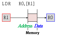
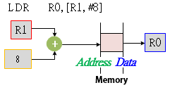
Example:
        LDR     R0, [R1]          ; R0 <= [R1] Load R0 with the word pointed by R1
        LDR     R0, [R1, #0]      ; R0 <= [R1+0] same as R0 = [R1]
        STR     R2, [R0, #4]      ; [R0 + 4] <= R2 Store the word in R2 to the location pointed by R0+4
Register
The offset is a general-purpose register (not the PC), that can be added to or subtracted from the base register. Register offsets are useful for accessing arrays or blocks of data.
- Load data from memory: LDR Rd, [Rn, Rm]
- Save data to memory: STR Rd, [Rn, Rm]
Example:
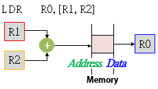
Example:
        LDR     R0, [R1, R2]      ; R0 <= [R1+R2]
        STR     R2, [R0, R4]      ; [R0+R4] <= R2
Scaled-Register
The offset is a general-purpose register (not the PC) shifted by an immediate value, then added to or subtracted from a base register.
The same shift operations used for data-processing instructions can be used (Logical Shift Left, Logical Shift Right, Arithmetic Shift Right and Rotate Right), but Logical Shift Left (LSL) is the most useful as it allows an array indexed to be scaled by the size of each array element.
Scaled register offsets are only available for the word and unsigned byte instructions.
- Load data from memory: LDR Rd, [Rn, Rm, LSL #imm]
- Save data to memory: STR Rd, [Rn, Rm, LSL #imm]
Example:
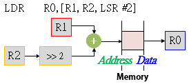
Example:
        LDR     R0, [R1, R2, LSL #2]  ; R0 <= [ R1 + (R2 * 4)]
        STR     R2, [R3, R4, LSR #4]  ; [R3 + (R4 / 16)] <= R2
Pre-Indexed Addressing
The effective address of an operand in the pre-indexed addressing mode is generated in the same way as in the offset indexed mode, and then the effective address is written back into Rn.
Immediate
The offset value is added to or subtracted from the address obtained from the register Rm. The result is used as the address for the memory access and is written back into the register Rm. The assembly language syntax for this mode is:
- Load data from memory: LDR Rd, [Rn, #imm]!
- Save data to memory: STR Rd, [Rn, #imm]!
Example:
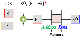
Example:
        LDR     R0, [R1, #2]!   ; R0 <= [ R1 + 2], R1 <= R1 + 2
        STR     R2, [R3, #4]!   ; [R3 + 4] <= R2, R3 = R3 + 4
Register
Syntax:
- Load data from memory: LDR Rd, [Rn, Rm]!
- Save data to memory: STR Rd, [Rn, Rm]!
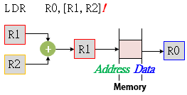
Example:
Scaled Register
Syntax:
- Load data from memory: LDR Rd, [Rn, Rm, LSL #imm]!
- Save data to memory: STR Rd, [Rn, Rm, LSL #imm]!
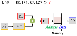
Example:
Post-Indexed Addressing
The effective address of the operand in the post-indexed addressing mode is the contents of Rn. The offset is then added to this address and the result is written back into Rn.
Immediate
The address obtained from the register Rn is used as the address for the memory access. The offset value is added to or subtracted from the address, and is written back into the register Rn. The assembly language syntax for this mode is:
- Load data from memory: LDR Rd, [Rn], #imm
- Save data to memory: STR Rd, [Rn], #imm
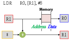
Example:
Register
Syntax:
- Load data from memory: LDR Rd, [Rn], Rm
- Save data to memory: STR Rd, [Rn], Rm
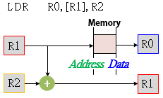
Example:
Scaled Register
Syntax:
- Load data from memory: LDR Rd, [Rn], Rm, LSL #imm
- Save data to memory: STR Rd, [Rn], Rm, LSL #imm
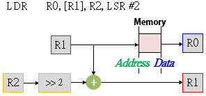
Example:
Pre-indexed and Post-indexed addressing modes are generalizations of the Autodecrement and Autoincrement addressing modes, respectively,
Summary of ARM's Indexed Addressing Modes
| Addressing Mode | Assembly Mnemonic | Effective Address | Final Value in R1 |
| Indexed, base unchanged | LDR R0, [R1, #d] | R1 + d | R1 |
| Pre-indexed, base updated | LDR R0, [R1, #d]! | R1 + d | R1 + d |
| Post-indexed, base updated | LDR R0, [R1], #d | R1 | R1 + d |
PC-Relative Addressing
PC-Relative addressing occurs in branch instruction, and access memory from current PC value plus or minus a numeric offset.
Syntax:
- Branch Instructions: B{L|X|LX|cond} <label>
- Load data from memory: LDR Rd, [PC, #imm]
- Save data to memory: STR Rd, [PC, #imm]
Example: