Tiva Lab 10: Using Ultrasonic Sensor for Distance Determination
Objective
Required Reading Materials
- Lesson 17: Timer - Input Edge-Count Mode
- Datasheet: HC-SR04 Ultrasonic: HCSR04.pdf
- Windows program for Telnet/Serial communication: PuTTY.exe http://www.chiark.greenend.org.uk/~sgtatham/putty/latest.html
- Lesson 05: Branches
Overview
An ultrasonic sensor is a great tool for all kinds of projects that need distance measurements. Obstacle avoidance is one example.
Ultrasonic sensor HC-SR04 is used in this lab to measure distance in the range of 2 cm to 400 cm with an accuracy of 3 mm. The sensor module consists of the control circuit and two ultrasonic sensors — one is the transmitter, and another is the receiver.
How Ultrasonic Sensors Work
An ultrasonic burst of energy is emitted from the transducer. This is known as a ping. The sound waves travel until reflected off of an object. The echoed sound wave returns to the transducer. The echo may be of smaller amplitude, but the carrier frequency should be the same as the ping. An external timer records the time of flight (the time that the sound waves take to travel to and from the object), which can be converted to distance when considering the speed of sound in air. As the transmitted sound waves propagate from the transducer, they spread over a greater range. In other words, the sound waves propagate from the transducer in the shape of a cone of angle q.
Limitations of Sonar Sensors
Sonar sensors are not ideal devices. They are limited to resolution, range, and the size of the object they can detect. The external timing circuits of some sonar sensor systems are subject to false echoes. Values returned by the sensor may not match the actual distance of the object. One solution is to take an average of your readings. For example, ping three times and taking an average. This method seems to reduce the effects of false triggers.
In this lab, you will learn Timer Input Capture and Universal Asynchronous Receiver transmitter (UART) communication methods. You will use Timer Input Capture to measure an input pulse width that is directly proportional to the distance measured by an ultrasonic sensor, and then send the result to the PC through the UART.
Required Components List
| HC-SR04 Ultrasonic Sensor Module | x 1 | |
| Breadboard | x 1 | |
 |
One 200Ω or 220Ω resistor | x 1 |
Circuit / Schematic Diagram and Sample Firmware Code
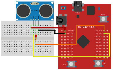
EK-TM4C123GXL LaunchPad
Connect the ultrasonic sensor with your Tiva TM4C123G LaunchPad
- Connect the "Trig" pin to GPIO PortF[3]
- Connect the "Echo" pin to Timer1A on PortF[2] with a 200Ω or 220Ω resistor
- Connect the "Vcc" pin to +5V or VBUS on the LaunchPad
- Connect the "Gnd" pin to the GND pin on the LaunchPad
Table 1: Pin Configurations:
| Device | Port.Pin | Signal Type | PCTL | Direction | Drive Mode |
|---|---|---|---|---|---|
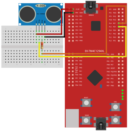
EK-TM4C1294XL LaunchPad
Connect the ultrasonic sensor with your Tiva TM4C1294 LaunchPad
- Connect the "Trig" pin to GPIO PortL[5]
- Connect the "Echo" pin to Timer0A on PortL[4] with a 200Ω or 220Ω resistor
- Connect the "Vcc" pin to the +5V pin on the LaunchPad
- Connect the "Gnd" pin to the GND pin on the LaunchPad
Table 1: Pin Configurations:
| Device | Port.Pin | Signal Type | PCTL | Direction | Drive Mode |
|---|---|---|---|---|---|
Procedure
- Create a new folder under the EE3450 folder and name it Lab10_Ultrasonic.
- Launch the Keil μVisio and create a new project. Save the project to the project folder you just created in the previous step and set the project name to Lab10_Ultrasonic.
- Add the Common and ezTivaLIB folders to the include paths, that is under the "Options for Target" setting.
- Add ezTiva LIB (ez123GLIB.lib or ez1294LIB.lib) into your project, increase the stack and heap size under the "startup_TM4cXXX.s (Startup)" setting.
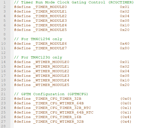
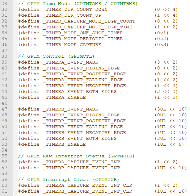
MyDefines.h
Add the following definitions to the MyDefines.h file:
Configurations
Write down the following configuration information in your report.
UART Connection and Configuration
GPIO Initialization and Configuration
GPIO Initialization Configuration
Next, we need to configure all the GPIO ports and pins that are used in the design.
According to the pin connections, complete the following GPIO configurations for each port. Fills the pin field by the value below:
- 0: Clean the bit
- 1: Set the bit
- x: Do not change the bit
- d: Do not care
For both TM4C123GXL and TM4C1294XL LaunchPads, the Port C [3:0] are used for JTAG/SWD. Therefore, when you configure Port C, you have to use bitwise operators to make sure your new configuration settings do not affect the JTAG/SWD function (PC3 ~ PC0).
Most of GPIO pins are configured as GPIOs and tri-stated by default (GPIOPCTL = 0, CPIOAFSEL = 0, GPIODIR = 0, GPIOPUR = 0, GPIOPDR = 0, GPIOODR = 0)
- Enable Clock to the GPIO Modules (RCGCGPIO register)
TM4C123G: SYSCTL->RCGCGPIO |= (_PORTs); |= binary = hex
8 4 2 1 8 4 2 1 7 6 5 4 3 2 1 0 bit Port F Port E Port D Port C Port B Port A port 0 0 -
TM4C1294: SYSCTL->RCGCGPIO |= (_PORTs); |= binary = hex
After enabling the clock signal, check the PRGPIO register until the corresponding bit is set to 1.8 4 2 1 8 4 2 1 8 4 2 1 8 4 2 1 15 14 13 12 11 10 9 8 7 6 5 4 3 2 1 0 bit Port Q Port P Port N Port M Port L Port K Port J Port H Port G Port F Port E Port D Port C Port B Port A port 0 - - -
In Assembly:
            LDR     R0, =SYSCTL_PRGPIO_R
Wait4GPIO   LDR     R1, [R0]
            TST     R1, #(__)
            BEQ     Wait4GPIO
In c:
while ( (SYSCTL->PRGPIO & ____ ) != ____ ) {}; - Unlock Port
TM4C123G: PD7 and PF0 are locked after reset.
TM4C1294: PD7 and PE7 are locked after reset
If those pins are used in the design, they must be unlocked first. To unlock the port, 0x4C4F434B must be written into the GPIOLOCK register and uncommit it by setting the GPIOCR register.
8 4 2 1 8 4 2 1 7 6 5 4 3 2 1 0 bit Port Pin 7 Pin 6 Pin 5 Pin 4 - Pin 3 Pin 2 Pin 1 Pin 0 pin Value in Hex Register Value to Register - - = ➤ GPIO ->LOCK = 0x4C4F434B - - = ➤ GPIO ->CR - - = ➤ GPIO ->LOCK = 0x4C4F434B - - = ➤ GPIO ->CR
Convert above configuration into registers
- GPIO Analog Mode Select
If any pin is used as an Analog signal (check Signal Type field on table 1), the appropriate bit in AMSEL must be set.
- 0: Digital signal
- 1: Analog signal
8 4 2 1 8 4 2 1 7 6 5 4 3 2 1 0 bit Port Pin 7 Pin 6 Pin 5 Pin 4 - Pin 3 Pin 2 Pin 1 Pin 0 pin Value in Hex Register Value to Register - - = ➤ GPIO ->AMSEL - - = ➤ GPIO ->AMSEL - - = ➤ GPIO ->AMSEL - - = ➤ GPIO ->AMSEL - - = ➤ GPIO ->AMSEL - - = ➤ GPIO ->AMSEL - - = ➤ GPIO ->AMSEL - GPIO Port Control (PCTL)
The PCTL register is used to select the specific peripheral signal for each GPIO pin when using the alternate function mode.
- 0: GPIO
- 1~0xF: Check the GPIO Pins and Alternate Function table
8421 8421 8421 8421 8421 8421 8421 8421 31~28 27~24 23~20 19~16 15~12 11~8 7~4 3~0 bit Port Pin 7 Pin 6 Pin 5 Pin 4 - Pin 3 Pin 2 Pin 1 Pin 0 pin Value in Hex Register Value to Register - - = ➤ GPIO ->PCTL - - = ➤ GPIO ->PCTL - - = ➤ GPIO ->PCTL - - = ➤ GPIO ->PCTL - - = ➤ GPIO ->PCTL - - = ➤ GPIO ->PCTL - - = ➤ GPIO ->PCTL - GPIO Alternate Function Select (AFSEL)
Setting a bit in the AFSEL register configures the corresponding GPIO pin to be controlled by PCTL peripheral function.
- 0: General I/O
- 1: Pin connected to the digital function defined in the PCTL register
8 4 2 1 8 4 2 1 7 6 5 4 3 2 1 0 bit Port Pin 7 Pin 6 Pin 5 Pin 4 - Pin 3 Pin 2 Pin 1 Pin 0 pin Value in Hex Register Value to Register - - = ➤ GPIO ->AFSEL - - = ➤ GPIO ->AFSEL - - = ➤ GPIO ->AFSEL - - = ➤ GPIO ->AFSEL - - = ➤ GPIO ->AFSEL - - = ➤ GPIO ->AFSEL - - = ➤ GPIO ->AFSEL - GPIO Pin Direction (DIR)
Set pin direction
- 0: Input pin
- 1: Output pin
8 4 2 1 8 4 2 1 7 6 5 4 3 2 1 0 bit Port Pin 7 Pin 6 Pin 5 Pin 4 - Pin 3 Pin 2 Pin 1 Pin 0 pin Value in Hex Register Value to Register - - = ➤ GPIO ->DIR - - = ➤ GPIO ->DIR - - = ➤ GPIO ->DIR - - = ➤ GPIO ->DIR - - = ➤ GPIO ->DIR - - = ➤ GPIO ->DIR - - = ➤ GPIO ->DIR - Internal Pull-Up Resistor (PUR), Pull-Down Resistor (PDR), and Open-Drain (ODR)
PUR: The pull-up control register
PDR: The pull-down control register
ODR: The open-drain control register
- 0: Disable
- 1: Enable
8 4 2 1 8 4 2 1 7 6 5 4 3 2 1 0 bit Port Pin 7 Pin 6 Pin 5 Pin 4 - Pin 3 Pin 2 Pin 1 Pin 0 pin Value in Hex Register Value to Register - - = ➤ GPIO -> - - = ➤ GPIO -> - - = ➤ GPIO -> - - = ➤ GPIO -> - - = ➤ GPIO -> - - = ➤ GPIO -> - - = ➤ GPIO -> - GPIO Digital Enable
Enables all the pins that are used in the design, including GPIO pins and alternate function pins.
- 0: Pin undriven
- 1: Enable pin
8 4 2 1 8 4 2 1 7 6 5 4 3 2 1 0 bit Port Pin 7 Pin 6 Pin 5 Pin 4 - Pin 3 Pin 2 Pin 1 Pin 0 pin Value in Hex Register Value to Register - - = ➤ GPIO ->DEN - - = ➤ GPIO ->DEN - - = ➤ GPIO ->DEN - - = ➤ GPIO ->DEN - - = ➤ GPIO ->DEN - - = ➤ GPIO ->DEN - - = ➤ GPIO ->DEN
Example Source Code
EK-TM4C123G LaunchPad - main.c
#include <stdio.h>
#include <stdlib.h>
#include <stdbool.h>
#include <stdint.h>

#include "TM4C123GH6PM.h"
#include "ez123G.h"
#include "MyDefines.h"

void Setup_UART(void);
void Setup_TIMER(void);
void Setup_GPIO(void);

void        UART0_PrintString(char*);
double      measureT(void);

char str[100];

int main(void)
{
    double      pulseWidth;
    float       distance;
    uint16_t    i = 0;

    Setup_123G_80MHz(); // Setup SystemClock to 80MHz
    Setup_TIMER();      // Setup Timer Input Capture on PORTF[2]
    Setup_UART();       // Setup UART on PA0 and PA1
    Setup_GPIO();       // Setup GPIOs

    sprintf(str,"Project for EE-3450: Ultrasonic Sensor \n\r");
    UART0_PrintString(str);

    while(1){
        // Set "Trig" pin to Low

        timer_waitMillis(500);      // Waiting for 500ms
        // Set "Trig" pin to High for 10ns

        timer_waitMicros(10);       // Waiting for 10ns
        // Set "Trig" pin to Low

        pulseWidth = measureT();    // Call measureT() to get the delta t on the "echo" pin
        // Calculate distance

        sprintf(str,"%d: width: %.2f us, distance: %6.2lf cm \n\r", ++i, pulseWidth * 1000000, distance);
        UART0_PrintString(str);
    }
}
//----------------------------------------------------------------------------------
double measureT(void)
{
    uint32_t highEdge,lowEdge;
    double   deltaT;

    /*Capture firstEgde i.e. rising edge*/
    //1. Clear GPTM Timer A Capture Mode Event by writing 1 to
    //   corresponding bit on GPTMICR (TIMER1->ICR) register

    //2. Waiting for capture rising edge event by check the GPTM Raw Interrupt Status
    //   GPTMRIS (TIMER1->RIS) register

    //3. Set the highEdge from GPTMTAR (TIMER1->TAR) registers

    /*Capture secondEgde i.e. falling edge*/
    //4. Clear GPTM Timer A Capture Mode Event by writing 1 to
    //   corresponding bit on GPTMICR (TIMER1->ICR) register

    //5. Waiting for capture falling edge event by check the GPTM Raw Interrupt Status
    //   GPTMRIS (TIMER1->RIS) register

    //6. Set the lowEdge from GPTMTAR (TIMERa->TAR) registers

    //7. Calculate deltaT = (highEdge - lowEdge) * (1/TimerFreq)
    //   Note: the deltaT must large than zero, cannot be negative value

    return deltaT;
}
//----------------------------------------------------------------------------------
void Setup_UART(void)
{
// Setup UART on 38400bps
#define UARTIBRD 00     // You need to calculate IBRD value
#define UARTFBRD 00     // You need to calculate FBRD value

    // 1. Enable clock to UART Module 0 (SYSCTL_RCGCUART)
    SYSCTL->RCGCUART |= (__);
    // allow time for clock to stabilize
    while((SYSCTL->PRUART & (__)) != (__)){};
    // 2. Disable UART by clearing UARTEN in UARTCTL register
    UART?->CTL &= ~(__);
    // 3. Write BRD to UARTIBRD and UARTFBRD register
    UART?->IBRD = UARTIBRD;
    UART?->FBRD = UARTFBRD;
    // 4. Write UART Line control (UARTLCRH register)
    //    8bit, No parity, 1-stop bit, Enable FIFO
    UART?->LCRH = (__);
    // 5. Configure the UART clock source (UARTCC register)
    UART?->CC = (__);   // Clock Source from System Clock
    // 6. Enable UART by clearing UARTEN in UARTCTL register
    UART?->CTL = (__); // Enable UART0, TXE, RXE
}
//----------------------------------------------------------------------------------
void Setup_TIMER(void)
{
    //* PF2: T1CCP0 (PCTL=07) both edge (edge-time mode)

    // 1 . Enable Clock for TIMER Module
    SYSCTL->RCGCTIMER |= (__);
    while ((SYSCTL->PRTIMER & (__)) != (__)) {}
    // 2. Disable TIMER
    TIMER?->CTL &= ~(__);  // Disable TimerA & TimerB
    // 3. Configure TIMER
    TIMER?->CFG = 0x04;         // Split into two 16-bit timers
    // 4. Configure Timer n Mode: GPTMTAMR
    TIMER?->TAMR = (__);
    // 5. Configure Timer Event Mode: rising-, falling-, or both-edges
    TIMER?->CTL &= ~(__);
    TIMER?->CTL |=  (__);  // Both edges
    // 6. Configure Load
    TIMER?->TAILR = 0xFFFF;
    //Set the prescaler to 0xFF
    TIMER?->TAPR = 0xFF;
    TIMER?->IMR = 0;
    // 7. Enable GPTM Timer
    TIMER?->CTL |= (__);  // Enable TimerB
}
//----------------------------------------------------------------------------------
void Setup_GPIO(void)
{
    // GPIO Initialization and Configuration
    // 1. Enable Clock to the GPIO Modules (SYSCTL->RCGCGPIO |= (_PORTs);)
    SYSCTL->RCGCGPIO |= (__);
    // allow time for clock to stabilize (SYSCTL->PRGPIO)
    while((SYSCTL->PRGPIO & (__)) != (__)){};
    // 2. Unlock PD7 and PF0 on TM4C123G; or PD7 on TM4C1294 (GPIOx->LOCK = 0x4C4F434B; and GPIOx->CR = _PINs;)
    // 3. GPIO Analog Mode Select (GPIOAMSEL)

    // 4. GPIO Port COntrol (GPIOPCTL)

    // 5. Clear AFSEL bits to 0 to select regular I/O

    // 6. GPIO Pin Direction (GPIODIR) 0 for input, 1 for output

    // 7. Set PUR bits to 1 to enable internal pull-up resistor
    // 8. Set DEN bits to 1 to enable data pins

}
//----------------------------------------------------------------------------------
void UART0_PrintString(char * s)
{
    // Code from Lab 09
}
EK-TM4C1294 LaunchPad - main.c
#include <stdio.h>
#include <stdlib.h>
#include <stdbool.h>
#include <stdint.h>

#include "TM4C1294NCPDT.h"
#include "ez1294.h"
#include "MyDefines.h"

void Setup_UART(void);
void Setup_TIMER(void);
void Setup_GPIO(void);

void UART0_PrintString(char*);
double measureT(void);

char str[100];

int main(void)
{
    double      pulseWidth;
    float       distance;
    uint16_t    i = 0;

    Setup_1294_80MHz(); // Setup SystemClock to 80MHz
    Setup_TIMER();      // Setup Timer Input Capture
    Setup_UART();       // Setup UART on PA0 and PA1
    Setup_GPIO();       // Setup GPIOs

    sprintf(str,"Project for EE-3450: Ultrasonic Sensor \n\r");
    UART0_PrintString(str);

    while(1){
        // Set "Trig" pin to Low

        timer_waitMillis(500);      // Waiting for 500ms
        // Set "Trig" pin to High

        timer_waitMicros(10);       // Waiting for 10ns
        // Set "Trig" pin to Low

        pulseWidth = measureT();    // Call measureT() to get delta t on the "echo" pin
        // Calculate distance

        sprintf(str,"%d: width: %.2f us, distance: %6.2lf cm \n\r", ++i, pulseWidth * 1000000, distance);
        UART0_PrintString(str);
    }
}
//----------------------------------------------------------------------------------
double measureT(void)
{
    uint32_t highEdge,lowEdge;
    double   deltaT;

    /*Capture firstEgde i.e. rising edge*/
    //1. Clear GPTM Timer A Capture Mode Event by writing 1 to
    //   corresponding bit on GPTMICR (TIMER0->ICR) register

    //2. Waiting for capture rising edge event by check the GPTM Raw Interrupt Status
    //   GPTMRIS (TIMER0->RIS) register

    //3. Set the highEdge from GPTMTAR (TIMER0->TAR) registers

    /*Capture secondEgde i.e. falling edge*/
    //4. Clear GPTM Timer A Capture Mode Event by writing 1 to
    //   corresponding bit on GPTMICR (TIMER0->ICR) register

    //5. Waiting for capture falling edge event by check the GPTM Raw Interrupt Status
    //   GPTMRIS (TIMER0->RIS) register

    //6. Set the lowEdge from GPTMTAR (TIMERa->TAR) registers

    //7. Calculate deltaT = (highEdge - lowEdge) * (1/TimerFreq)
    //   Note: the deltaT must large than zero, cannot be negative value

    return deltaT;
}
//----------------------------------------------------------------------------------
void Setup_UART(void)
{
// Setup UART on 38400bps
#define UARTIBRD 00     // You need to calculate IBRD value
#define UARTFBRD 00     // You need to calculate FBRD value

    // 1. Enable clock to UART Module 0 (SYSCTL_RCGCUART)
    SYSCTL->RCGCUART |= (__);
        // allow time for clock to stabilize
    while((SYSCTL->PRUART & (__)) != (__)){};
    // 2. Disable UART by clearing UARTEN in UARTCTL register
    UART?->CTL &= ~(__);
    // 3. Write BRD to UARTIBRD and UARTFBRD register
    UART?->IBRD = UARTIBRD;
    UART?->FBRD = UARTFBRD;
    // 4. Write UART Line control (UARTLCRH register)
    //    8bit, No parity, 1-stop bit, Enable FIFO
    UART?->LCRH = (__);
    // 5. Configure the UART clock source (UARTCC register)
    UART?->CC = (__);   // Clock Source from System Clock
    // 6. Enable UART by clearing UARTEN in UARTCTL register
    UART?->CTL = (__); // Enable UART0, TXE, RXE
}
//----------------------------------------------------------------------------------
void Setup_TIMER(void)
{
    //* PL4: T0CCP0 (PCTL=03) both edge (edge-time mode)

    // 1 . Enable Clock for TIMER Module
    SYSCTL->RCGCTIMER |= (__);
    while ((SYSCTL->PRTIMER & (__)) != (__)) {}
    // 2. Disable TIMER
    TIMER?->CTL &= ~(__);     // Disable Timer
    // 3. Configure TIMER
    TIMER?->CFG = 0x04;         // Split into two 16-bit timers
    // 4. Configure Timer n Mode: GPTMTAMR
    TIMER?->TAMR = (__);
    // 5. Configure Timer Event Mode: rising-, falling-, or both-edges
    TIMER?->CTL &= ~(__);
    TIMER?->CTL |=  (__);     // Both edges
    // 6. Configure Load
    TIMER?->TAILR = 0xffff;
    //Set the prescaler to 0xFF
    TIMER?->TAPR = 0xFF;
    TIMER?->IMR = 0;
    // 7. Enable GPTM Timer
    TIMER?->CTL |= (__);      // Enable Timer
}
//----------------------------------------------------------------------------------
void Setup_GPIO(void)
{
    // GPIO Initialization and Configuration
    // 1. Enable Clock to the GPIO Modules (SYSCTL->RCGCGPIO |= (_PORTs);)
    SYSCTL->RCGCGPIO |= (__);
    // allow time for clock to stabilize (SYSCTL->PRGPIO)
    while((SYSCTL->PRGPIO & (__)) != (__)){};
    // 2. Unlock PD7 and/or PF0 on TM4C123G (GPIOx->LOCK = 0x4C4F434B; and GPIOx->CR = _PINs;)
    // 3. GPIO Analog Mode Select (GPIOAMSEL)

    // 4. GPIO Port COntrol (GPIOPCTL)

    // 5. Clear AFSEL bits to 0 to select regular I/O

    // 6. GPIO Pin Direction (GPIODIR) 0 for input, 1 for output

    // 7. Set PUR bits to 1 to enable internal pull-up resistor
    // 8. Set DEN bits to 1 to enable data pins

}
//----------------------------------------------------------------------------------
void UART0_PrintString(char *s)
{
    // Code from Lab 09
}
Lab Experiments
Exp #10.1: Object Distance Measurement
SONAR (Sound Navigation and Ranging) uses an ultrasonic signal to determine the presence and distance of objects. The HC-SR04 sensor module includes ultrasonic transmitter, receiver and control circuit. The ultrasonic transmitter emits 40 kHz sound pulses, and the receiver receives the return echo signal. The idea behind distance estimation is that objects reflect sound and that the time between emitting a sound pulse and receiving an echo can be translated into distance given the speed of sound through air.
The HC-SR04 sensor documentation provides a detailed description of how it operates, but a few points are worth emphasizing here:
- The HC-SR04 sensor uses two signal pins, one is for trigger and another is for receiving echo signal. The "trigger" pin is connected to the output pin of GPIO, and the "echo" pin is attached to the Input Capture pin of Timer with a 200Ω (or 220Ω) resistor to protect the Tiva LaunchPad.
- The HC-SR04 sensor must be "triggered" in order to enable pulsing. Therefore, you need to set the GPIO output pin high and then low. The sensor documentation discusses how long the trigger pulse should be.
- The echo signal received from the sensor will rise and then fall on the "echo" pin. The distance between these two edges is directly proportional to the round-trip distance between the sensor and the object. Input capture when properly configured to Edge-Time mode will identify the edges of the signal and set TIMERn_TAR_R to the current counter value when the events/edges are detected. The difference in counter values represents the signal's pulse width as time. The actual amount of time can be determined when the system clock frequency is used to compute the amount of time each counter value represents.
- After you calculate the value, send the distance in centimeters (cm) to your PC through UART.
Step 1: UART communication
You need to configure the UART function in Tiva LaunchPad. Both the LaunchPad and PC UARTs must be configured for the same baud rate. The following setting must be used in this part:
- Baud rate: 38400 bps
- Data length: 8-bit
- Stop bit: 1-bit
- Parity check: None
Step 2: Determine the Sensor Signal's Width
Read HC-SD04 documentation to get an understanding of what should happen on Pin2 of PORTF. Using input capture on Timer, determine the width of the HC-SR04 pulses in terms of the difference between the rising edge and falling edge. Send this delta t (\(dt\)) to the PC.
Step 3: Continuous Distance Determination
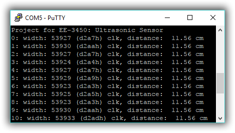
You should have mastered pulse width calculations by now. Perform a distance estimation every 500 ms and display the pulse width in time counts, in milliseconds or in clock cycles (0 is okay for pulse widths below 1 msec), and a distance calculation in centimeters on the PC (using the PuTTY program).
Example output on the PuTTY:
Exp #10.2: Emergency Stop Motor
Add a PWM function to the system, and connect a motor to the PWM signal through a motor driver. Control the motor speed according to the following conditions:
- If there is no object in the front of the fan, or if the distance between the fan and the object is more than 20 cm, then turn the fan speed to 100%.
- If any object is close to the fan within 20 cm ~ 10 cm, adjust the fan speed to 50%.
- Stop the fan when the object is within 10 cm.
Questions
- In the UART protocol, how many bits are NECESSARILY added into a data package for the interfacing to be successful? What is the function of those bits?
- Assume the system clock is 12 MHz. What is the baud rate if UART0_IBRD_R equals 2 and UART0_FBRD_R equals 32?
- Assume the system clock is 32 MHz. What values should you put in UART0_IBRD_R and UART0_FBRD_R to make a baud rate of 115200 bit/sec?
- A UART is configured as 1000,8N1, what is the bandwidth in bytes/sec?
- Two devices are using the UART protocol to exchange data. Describe what happens if device A sends data using a baud rate that is twice as fast as the received by device B?
- Two devices are using the UART protocol to exchange data. Describe what happens if device B receives data using a baud rate that is twice as fast as the sent by device A?
