Capacitors
Capacitors are a simple passive devices that can store an electrical charge on their plates when connected to a voltage source, much like a rechargeable battery. There are many different kinds of capacitors available, from very small capacitor beads used in resonance circuits to large power factor correction capacitors, but they all do the same thing, they story charge.
Types of Capacitors
The capacitor is a fundamental component for influencing the behavior of electronic circuits. It has applications in analog and digital circuits and at voltages from less than one volt to several thousand volts.
Designers have a variety of capacitor technologies at their disposal, differentiated primarily by the type of dielectric. This influences key aspects such as the capacitance value and size (volume) of the device, as well as energy efficiency. When combined with critical dimensions including the thickness of the dielectric, the capacitor's maximum voltage rating, and insulating capability can also be affected.
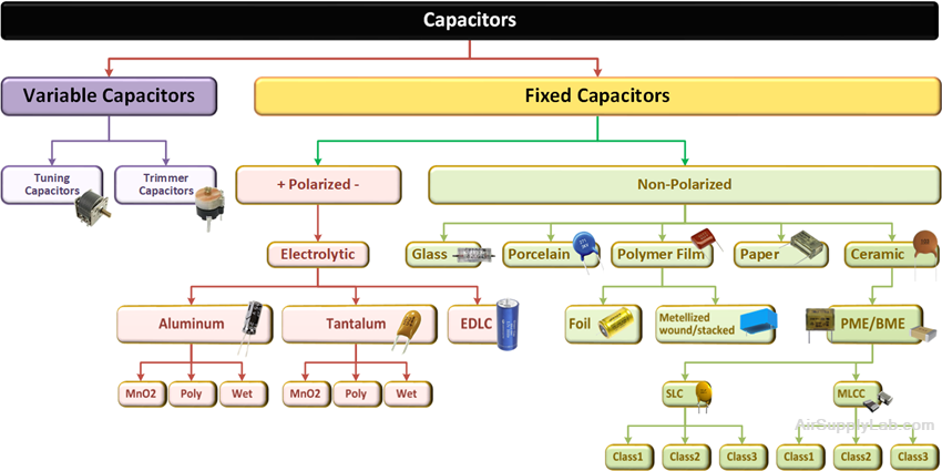
Figure 1: Overview of Capacitor Technologies
Variable and Fixed Capacitors
Fixed Capacitors
A fixed capacitor is constructed in such a manner that it possesses a fixed value of capacitance that cannot be adjusted. A fixed capacitor is classified according to the type of material used as its dielectrics, such as paper, oil, mica, or electrolyte.
Variable Capacitors

Figure 2: Schematic Symbol for a Variable Capacitor
Variable capacitors are pretty much just as they are named, and their capacitance can change by physically or electronically moving the plates.
Tuning Capacitors
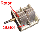
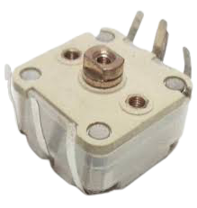
Tuning capacitors are a popular type of variable capacitors. They contain a stator, a rotor, a frame to support the stator, and a mica capacitor. The stator is a stationary part and the rotor rotates by the movement of a movable shaft. The rotor plates when moved into the slots of the stator, they come close to form plates of a capacitor. When the rotor plates sit completely in the slots of the stator then the capacitance value is maximum and when they don't, the capacitance value is minimum.
Tuning capacitors are commonly used in radios where you tune into a radio station. Originally, radios had a knob that could be turned changing the distance between the capacitor's plates.
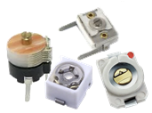
Trimmer Capacitors
Polar and Non-Polar Capacitors
One of the main distinctions between various types of capacitors is whether they are polarised or not. The use of polarity and non-polarized capacitors is determined by whether the nature of the dielectric is reversible.
Polarised Capacitor
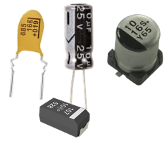
Figure 3.1: Polarised Capacitors

Figure 3.2: Schematic Symbols for
a Polarised Capacitor
Essentially a polarised capacitor is one that must be run with the voltage across it in a certain polarity. Most of the polarity capacitors use electrolytes as the dielectric, which makes the polarity capacitor have larger capacitance than other capacitors with the same volume.
Some of the more popular types of polarised capacitors include aluminum electrolytic and tantalum. These are marked to indicate the positive or negative terminal, and they should only be operated with a voltage bias in this direction — reverse bias can damage or destroy them. As capacitors perform many tasks like coupling and decoupling, there will be a permanent DC voltage across them, and they will pass only any AC components.
Non-Polarised Capacitor
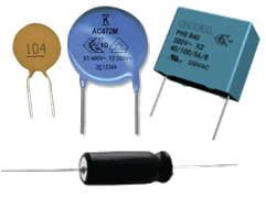
Figure 4.1: Non-Polarised Capacitors

Figure 4.2: Schematic Symbols for
a Non-Polarized Capacitor
The other form of the capacitor is a non-polarised or non-polar capacitor. This type of capacitor has no polarity requirement, and it can be connected either way in a circuit. Ceramic, plastic film, silver mica, and many other capacitors are non-polar or non-polarized capacitors.
How to Select Non-polarized Capacitors
Non-polarized capacitors are very convenient to be selected and used. You can directly select the capacitors with the same model and the same specifications. If none of the above conditions are met, you can refer to the following methods:
- Choose a reasonable capacitor accuracy. In most cases, the capacity requirements are not very high, and it is acceptable to have a capacity roughly the same as reference capacity. In the oscillation circuits, filtering circuits, delay circuits, and tone circuits, the absolute value of the error needs to be within 0.3%-0.5%.
- Select the capacitor according to the circuit requirements. The paper capacitor is generally used for the low-frequency AC bypass circuit. The mica capacitor or the ceramic capacitor are generally used in circuits of high frequency or high voltage.
- Capacitors can be selected with a rated voltage greater than or equal to the actual needs.
- High-frequency capacitors cannot be replaced by low-frequency capacitors.
- Consider the operating temperature, working range, temperature coefficient of the capacitor according to the application occasion.
- The series or parallel method can be used when the nominal capacity cannot be met, but the voltage added to the capacitor should be less than the withstand voltage of the capacitor.
Are Capacitor Types Interchangeable
Polarized capacitors must be connected with the correct polarity. Otherwise, capacitors explode. The non-polarized capacitor can connect in both directions. The polarized capacitor can only be used in DC. The non-polarized capacitor can be used in both AC and DC.
Eventually, you can replace a polarized capacitor with a non-polarized one. But you can't replace a non-polarized capacitor with a polarized one. Also, you should be careful about ripple current capability.
Major Capacitor Applications
Decoupling
The most prevalent use of capacitors is to decouple a system, such as an integrated circuit, from sudden changes, including transfers of energy, within the power supply. Connecting a decoupling capacitor between supply voltage connection and ground in an Integrated Circuit (IC), close to the IC itself, helps maintain a stable voltage level and supply fast power to the IC when needed.
Filtering
The second most common capacitor application is in filtering to remove signals at unwanted frequencies.
- By exploiting the capacitor's inherently high impedance at low frequencies and reducing impedance at higher frequencies, a resistor-capacitor (RC) filter can be designed to remove high-frequency interference such as noise in analog signals or to protect circuitry unwanted AC voltages applications, such as AM radio, cellar telephone, or IC switching noise applications.
- By combining capacitive, resistive, and inductive elements (inductors display increasing resistance at higher frequencies), analog filters can be built with low-pass, high-pass, band-pass or band-stop properties with various cut-off frequencies and selectivity characteristics.
Coupling
Because capacitors do not conduct DC currents, they are often used to separate different voltage levels from each other by blocking DC voltages. Since AC signals can pass through capacitors, this property is used in circuits such as multi-stage amplifiers. Signals are allowed to pass through but to separate voltage levels.
Timing and Waveshaping
The manner in which a capacitor charges and discharges through a resistor can be exploited for various timing purposes, such as introducing a delay or changing the shape of a waveform.
Oscillators
Together with inductive components, capacitors can be used to build oscillators for generating accurate sinusoidal signals.
Different Materials and Applications of Capacitors
The differing properties of various capacitor technologies allow designers to select the optimum device type of any given application based on criteria such as operating voltage, required capacitance, device size, and frequency response. Other characteristics, such as aging (drying of wet electrolyte) causing loss of capacitance, maximum recommended operating temperature, flammability, and self-healing properties, are also important factors influencing device selection. In some cases, special low ESR devices that feature minimal parasitic resistance may be required, for example, to minimize power losses in high current applications.
Power Capacitors
Ceramic Capacitors
Ceramic dielectrics and ceramic capacitors using these dielectrics are divided into three classes.
- Class 1: High stability and low losses. Compensates for the influence of temperature in resonant circuit applications. They are used in such applications as oscillators and filters where low losses, capacitance drift compensation, and high stability are required.
- Class 2: Has high volumetric efficiency, but also has higher losses and non-linear capacitance-temperature characteristics. They are used for a buffer, by-pass, and coupling/decoupling applications.
- Class 3: Has high volumetric efficiency, but also has poor accuracy and stability and a low dissipation factor. Class 3 ceramic capacitors are typically used for decoupling or in other power supply applications where accuracy is not an issue. However, they must not be used in applications where spikes are present as these may damage the capacitor if they exceed the rated voltage.
Multilayer Ceramic Capacitor (MLCC)
Film Capacitors
Plastic film capacitors are non-polarized capacitors with an insulating plastic film as a dielectric. The dielectric films are drawn to a thin layer and are not destroyed by breakdowns or shorts between electrodes. The direct contact gives the films the advantage of having very short current paths. Has low leakage. Suitable for applications with high surge currents.
Film capacitors can operate at relatively high temperatures, have high insulation resistance, have good stability, and are available in tolerances as tight as 0.5%. The self-healing property of metalized films is useful in some applications, where surge voltages might happen occasionally. Three main construction techniques are used: wound foil, metalized film, stacked film.
- Wound Foil Capacitors
A wound foil capacitor is made of two aluminum foils separated by sheets of dielectric and rolled into a compact cylinder. - Metalized Film Capacitors
Metalized film capacitors are made by vacuum deposition of aluminum 0.1 μm thick directly onto the dielectric film. The pattern is basically that of an extended foil configuration. - Stacked Film Capacitors
Stacked film capacitors are of newer construction. Metallised films are wound onto a large cylinder, then cut into rectangular sections. Connections are made to alternate electrodes on opposite ends, resulting in a stack of the metalized film connected in parallel. The structure is similar to that of multilayer ceramic capacitors, except the dielectric is much thinner. This compensates for the low permittivity of film dielectrics and produces a much better capacitance/volume ratio. Stacked film chip capacitors are an alternative to multilayer ceramic capacitors in some applications.
Recommended Applications for Film Capacitors
- Polystyrene film (KS) has excellent electrical characteristics. The loss angle of polystyrene film capacitors is low over a wide frequency range but the electrodes degrade performance with higher capacitance values as frequency increases. As a major drawback, the maximum ambient temperature of KS capacitors is only 85 °C. Also, capacitors over 10 nF tend to be rather bulky. Solvents affect the film, so sealed encapsulation is sometimes needed.
- Polypropylene film (KP) is another excellent choice for precision and HF applications. Polypropylene has a higher operating temperature (125 °C) and capacitors can be made smaller.
Electrolytic Capacitors
Aluminium Electrolytic Capacitors
Tantalum Electrolytic Capacitors