KB08: The Digital Oscilloscope
Objectives
To become familiar with the oscilloscope, a ubiquitous instrument for observing and measuring electronic signals.
Required Reading Materials
- Agilent 1000 Series Oscilloscopes: Uers's Guide
- Agilent 33120A 15 MHz Function / Arbitrary Waveform Generator: User's Guide
Components Required
| Component/Device | Description | Quantity |
|---|---|---|
 |
Agilent DSO1012A Oscilloscope (100 MHz, 2 GSa/S) | × 1 |
| Agilent 33120A 15 MHz Function/Arbitrary Waveform Generator | × 1 | |
 |
Cable, BNC to Alligator Clip | × 2 |
 |
Cable, Pomona, BNC to BNC | × 1 |
Background
Agilent DSO1012A Oscilloscope

The Agilent DSO1012A oscilloscope unlocks a powerful world of electronic measurements. Beyond just voltages, it can analyze frequencies, timings, phase shifts, and even signal distortions. Mastering this tool can be a game-changer in various scientific disciplines.
This guide focuses on the oscilloscope's essential functions:
Visualizing Signals:
- Time windows: Imagine capturing tiny slices of time, each starting at the same "trigger point" on the signal. These slices are then stacked on top of each other to create the familiar waveform on the screen.
- Timebase: This controls how much time each horizontal division on the screen represents. Think of it as zooming in or out on the timeline.
- Triggering: This tells the oscilloscope when to start capturing each time window. Proper triggering ensures you see the desired part of the signal clearly.
- Vertical controls: These adjust how much voltage each vertical division represents, essentially setting the "height" of the displayed signal.
Understanding Key Measurements:
- Voltage: Measure DC (steady) or AC (changing) voltages on both channels.
- Frequency: Determine how often a signal repeats itself (e.g., cycles per second).
- Time: Measure the duration of pulses or gaps in the signal.
- Phase: Compare the timing of two signals relative to each other.
- Harmonic distortion: Analyze the presence of unwanted "harmonics" that distort the original signal.
Additional Features:
- Automatic Measurements: Quickly get readings for common parameters like voltage and frequency.
- Waveform Math: Add, subtract, or even perform Fourier analysis on captured signals.
- Mask Testing: Verify if your signal falls within predefined limits.
- Data Storage and Connectivity: Save waveforms and measurements for later analysis or share them via USB.
Agilent 33120A 15 MHz Function/Arbitrary Waveform Generator
The Agilent 33120A is more than just a function generator; it's a versatile tool for creating and manipulating electronic signals with impressive accuracy and control. Whether you're an experienced engineer or a curious student, this 15 MHz powerhouse can elevate your projects to new levels.
Key Features:
- Precision waveforms: Generate standard waveforms like sine, square, ramp, triangle, and noise with exceptional stability and low distortion.
- Customizable creations: Craft intricate, user-defined waveforms using the 12-bit resolution and 40 MSa/s sampling rate, opening doors to unique signal simulations.
- Modulation mastery: Add internal AM, FM, FSK, and burst modulation to your waveforms, mimicking real-world signal behaviors without external equipment.
- Sweep and burst versatility: Investigate dynamic signal changes with linear and logarithmic sweep functions, or create pulsed outputs with internal/external burst control.
- Intuitive operation: Front-panel knobs and keys provide fast access to essential functions, streamlining your workflow.
- Connectivity options: Communicate with the instrument via GPIB, RS-232, or the IntuiLink software for remote control and advanced analysis.
Applications:
- Testing circuits and componentsSimulating real-world signals
- Generating training signals for educational purposes
- Characterizing audio and communication systems
- Performing power integrity measurements
Experiments
The following exercise is intended to familiarize you with the important functions of the oscilloscope.
KB08.1 Default Settings of Oscilloscope
To operate the Agilent DSO1012A Oscilloscope and configure it according to your specific requirements, follow the detailed lab instructions provided below. These steps will guide you through powering on the device, setting up channels, adjusting waveform positions, and configuring trigger settings to display and analyze square waves effectively.
- Power on the Oscilloscope
- Press the Power Switch on the front panel. Wait for the display to complete initialization.

- Press the Power Switch on the front panel. Wait for the display to complete initialization.
- Load the default oscilloscope setup
You can recall the factory default setup any time you want to return the oscilloscope to its original setup.
- Press the front panel Default Setup key.
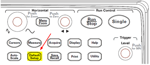
- When the Default menu appears, press Menu On/Off to turn off the menu.
- Press the front panel Default Setup key.
- Turn on Both Channels and Configure Channels for DC and Probe Attenuation
- Press the buttons labeled 1 next to the channel input BNC connectors to turn on channel 1.
- You should see a green light on the button indicating that channel 1 is active.
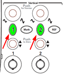
- When you press the corresponding channel button, the menu will display on the screen.
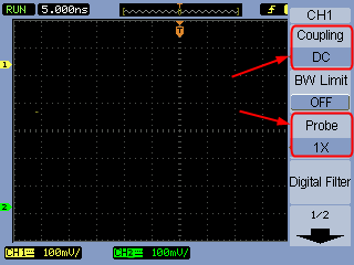
- Select Coupling and choose DC. This ensures the scope displays the direct current component of the signal.
- Select the Probe option and set the Attenuation to 1X for the channel. This ensures the displayed voltage matches the actual signal voltage.
- Repeat the same process for Channel 2.
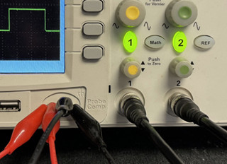
- Connect Channels to Prob Comp
- Locate the Prob Comp terminals usually found at the front panel.
- Connect the probe of Channel 1 and Channel 2 to the Prob Comp terminal.
- You should see two square waves displayed on the screen.
- Adjust Amplitude/Division to 2V/div
- For Channel 1, use the Vertical Scale knob to adjust the amplitude to 2V/div. This defines the voltage represented by each vertical division on the screen.
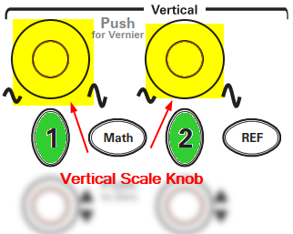
- Repeat the process for Channel 2, ensuring both channels display waveforms at 2V/div.

- For Channel 1, use the Vertical Scale knob to adjust the amplitude to 2V/div. This defines the voltage represented by each vertical division on the screen.
- Adjust Waveforms Position
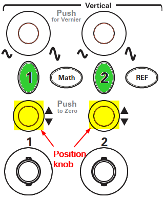
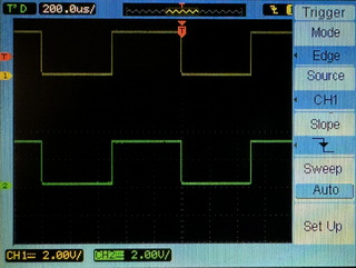
- Press buttons labeled 1 to select Channel 1, then adjust the Position knop to move the yellow waveform line on the upper level of the screen
- Press buttons labeled 2 to select Channel 2, then adjust the Position knop to move the green waveform line on the lower level of the screen
- Change the Horizontal Scale and Position
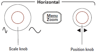
- The Horizontal Scale knob — changes the oscilloscope’s time per division setting using the center of the screen as a reference.
- Adjust the Horizontal Scale knob (Time/Div knob) to zoom in or out until at least one complete cycle of the CH1 waveform is visible on the screen.
- The horizontal position knob — changes the position of the trigger point relative to the center of the screen.
- Use the Horizontal Position knob to shift the waveform horizontally until the first falling edge of the channel 1 waveform aligns with the first vertical dashed line on the screen. This ensures the waveform starts at the desired position on the screen.
- The Horizontal Scale knob — changes the oscilloscope’s time per division setting using the center of the screen as a reference.
- Change the Trigger Signal and Slope
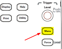
- Press the Trigger Menu button to access trigger settings.
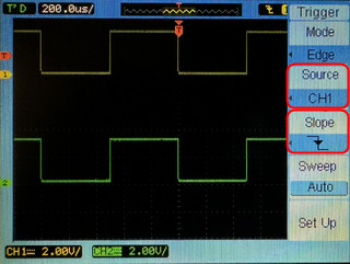
- Select Source and choose CH1 as the trigger source. This makes the scope trigger events occurring on the CH1 waveform.
- Find the Slope option and select Falling to trigger on the falling edge of the channel 1 signal. This triggers the scope when the CH1 signal passes from high to low voltage.
- Press the Trigger Menu button to access trigger settings.
- Adjust the Trigger Level
- Use the Trigger Level knob to position the trigger level between the high and low levels of the Channel 1 signal. This determines which specific point on the waveform triggers the display, and ensures a stable waveform display.
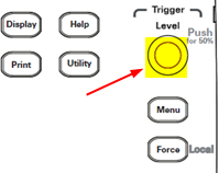
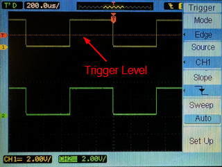
- Use the Trigger Level knob to position the trigger level between the high and low levels of the Channel 1 signal. This determines which specific point on the waveform triggers the display, and ensures a stable waveform display.
These steps will guide you through the basic setup and operation of the Agilent DSO1012A Oscilloscope for displaying and analyzing two square waves. Always refer to the oscilloscope’s user manual for detailed information about each function and feature to ensure accurate and safe operation.
After completing the settings, please have your instructor verify your results.