KB06: Descriptions of IC's Used in Digital Logic Labs
This section does not include gate chips: 7400, 02, 04, 08, 10, 32, and 86.
Notational note: On the Standard IC Symbol sheet, a 「bubbled」 pin indicates an active-low input or output. Here, a / preceding the pin name means the same thing. Thus, /CLR = CLR. This specifically refers to the voltage at the pin. Inside the symbol — on the other side of the bubble from the pin — it would be shown as CLR.
7470 AND Gated
7474 Dual D-Type Flip-Flop
7476 Dual J-K Flip-Flop
7483 4-bit Bniary Adder with Fast Carry
7493 4-bit Binary Asynchronous (Ripple) Counter
74151 8-o-1 Multiplexer
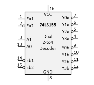
74155 Dual 2-to-4 Decoder
The 74155 can be used in two ways:
- dual 2-to-4 decoder


- 3-to-8 decoder

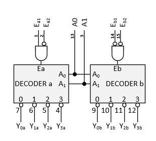
As a dual 2-to4 decoder, it can be thought of as separate decoder with common select input A1, A0. Since the select inputs are common, the decoders are not really independent, and as such, they are of limited usefulness. The really utility of this chip for decoding (rather than demultiplexing) purposes is as a 3-to-8 decoder.
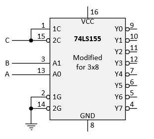
The enable inputs for the 3-to-8 configuration are /1G (pin 2) and /2G (pin14). These active-low inputs must both be low for the decoder to operate. If either or both are high, then all 8 outputs go inactive. To operate the decoder continuously, just ground both /1G and /2G.
The decoder needs a third select input, in addition to B and A. This is formed by connecting the inputs 1C and /2C together and calling the result "C". The select inputs are now CBA (with C the MSb).
The 8 outputs will be designated Y7...Y0. These are related to pin numbers as follows:
| 3-to-8 Outputs | Y7 | Y6 | Y5 | Y4 | Y3 | Y2 | Y1 | Y0 |
|---|---|---|---|---|---|---|---|---|
| Pin Numbers | 4 | 5 | 6 | 7 | 12 | 11 | 10 | 9 |
Standard pin labels (Y0a…Y3a, Y0b…Y3b) shown on the 74155 diagram are confusing when the 74155 is used as a 3-to-8 decoder. To avoid confusion, just ignore them and rely only on pin numbers to identify decoder outputs (as shown above). These decoder outputs are active LOW. Thus, if the decoder is enabled and select inputs are CBA = 011, then Y3 ⇒ 0, while the 7 outputs that are not selected remain high;
| Y7 | Y6 | Y5 | Y4 | Y3 | Y2 | Y1 | Y0 |
|---|---|---|---|---|---|---|---|
| H | H | H | H | L | H | H | H |
If the decoder is not enabled (either /G1 or /G2 or both are high), then all Y's stay high
74157 Quad 2-to-1 Multiplexer
74161 Synchronous 4-bit Binary Counter with Parallel Load
74179 4-bit Shift Register with Parallel Load
74194 4-bit Bidirectional Shift Register with Parallel Load
74195 4-bit Shift Register with Parallel Load