Lesson 06: Standard Combinational Components
6.1 Comparators
6.2 Decoders
6.3 Encoders
6.4 Multiplexers
Multiplexers
The multiplexer or MUX is a digital switch, also called a data selector. It is a Combinational Circuit that selects binary information from one of many input lines and directs it to a single output line. Multiplexers operate like very fast-acting multiple position rotary switches connecting or controlling multiple input lines called "channels" one at a time to the output. The selection of a particular input line is controlled by a set of selection lines. Normally, there are 2n input lines and n selection lines whose bit combinations determine which input is selected.
The below figure shows the block diagram of a multiplexer consisting of n input lines, m selection lines, and one output line. If there are m selection lines, then the number of possible input lines is 2m. Alternatively, we can say that if the number of input lines is equal to 2m, then m selection lines are required to select one of n (consider 2m = n) input lines.
This type of multiplexer is referred to as 2n × 1 multiplexer or 2n-to-1 multiplexer. For example, if the number of input lines is 4, then two select lines are required. Similarly, to select one of 8 input lines, three select lines are required.
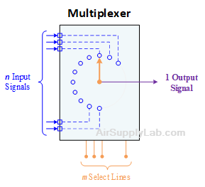
Figure 1: n-to-1 MUX
Generally, the number of data inputs to a multiplexer is a power of two such as 2, 4, 8, 16, etc. Some of the most frequently used multiplexers include 2-to-1, 4-to-1, 8-to-1, and 16-to-1 multiplexers.
These multiplexers are available in TTL chip IC forms with different input and select line configurations. Some of the available multiplexer ICs include 74157 (Quad 2-to-1 MUX), 78158 (Quad 2-to-1 MUX with inverse output), 74153 (4-to-1 MUX), 74152 (8-to-1 MUX), and 74150 (16-to-1 MUX).
2-to-1 MUX
| S | Y |
|---|---|
| 0 | I0 |
| 1 | I1 |
| S | I1 | I0 | Y |
|---|---|---|---|
| 0 | 0 | 0 | 0 |
| 0 | 0 | 1 | 1 |
| 0 | 1 | 0 | 0 |
| 0 | 1 | 1 | 1 |
| 1 | 0 | 0 | 0 |
| 1 | 0 | 1 | 0 |
| 1 | 1 | 0 | 1 |
| 1 | 1 | 1 | 1 |
Figure 2: 2-to-1 Multiplexer
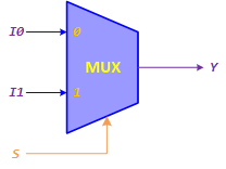
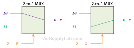
A 2-to-1 multiplexer connects one of two 1-bit sources to a common destination, as shown in Figure 2(a). The circuit has two inputs I0 and I1, one select input S and one output Y. The 2-to-1 multiplexer functions as follows:
- When S = 0, the I0 is connected to output Y.
- When S = 1, the I1 will be connected to Y.
Figure 2(c) is the function table of the 2-to-1 multiplexer. From the function table, we can build a truth table as shown in Figure 2(c). You can see when the selection line S is 0, the input I0 passes its data to the output Y, while I1 is blocked; when the selection line S is 1, the reverse happens and now input I1 passes data to the output Y while input I0 is blocked.
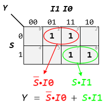
(a) K-Map for 2-to-1 MUX
(b) Logic Circuit of 2-to-1 MUX
Figure 3: Design 2-to-1 MUX
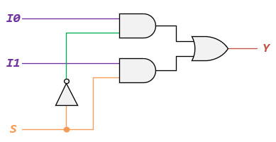
The output Y of the 2-to-1 multiplexer can be realized by using K-Map to obtain a simplified Boolean expression, as shown in Figure 3(a). The Boolean expression for this 2-to-1 Multiplexer is: $Y = \overline S \cdot I0 + S \cdot I1$.
Then you can see that the logic circuit of 2-to-1 multiplexer can be implemented by using logic gates as shown in Figure 3(b). It consists of two AND gates, one NOT gate, and one OR gate. When the select line, S = 0, the output of the lower AND gate is zero, but the output of the upper AND gate is I0. Thus, the output generated by the OR gate is equal to I0. Similarly, when S = 1, the output of the upper AND gate is zero, but the output of the lower AND gate is I1. Therefore, the output of the OR gate is I1.
4-to-1 MUX
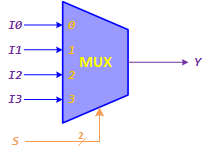
Here is a block diagram and abbreviated truth table for a 4-to-1 Multiplexer as shown in Figure 4.

| S | Y |
|---|---|
| 00 | I0 |
| 01 | I1 |
| 10 | I2 |
| 11 | I3 |
| S | I3 | I2 | I1 | I0 | Y |
|---|---|---|---|---|---|
| S1 S0 | |||||
| 0 0 | X | X | X | 0 | 0 |
| X | X | X | 1 | 1 | |
| 0 1 | X | X | 0 | X | 0 |
| X | X | 1 | X | 1 | |
| 1 0 | X | 0 | X | X | 0 |
| X | 1 | X | X | 1 | |
| 1 1 | 0 | X | X | X | 0 |
| 1 | X | X | X | 1 |
Figure 4: 4-to-1 Multiplexer
The Boolean expression of the 4-to-1 multiplexer is $Y = \overline {{S_1}} \cdot \overline {{S_0}} \cdot I0 + \overline {{S_1}} \cdot {S_0} \cdot I1 + {S_1} \cdot \overline {{S_0}} \cdot I2 + {S_1} \cdot {S_0} \cdot I3$.