Lesson 01: Definitions and Units
1.1 Definitions
Understanding electric charges, fields, voltage, and current is fundamental to studying circuit analysis. Let's delve into each concept with detailed examples and explanations.
Note: In the electrical circuit analysis, the capital letter usually denotes constant values, and the lowercase letter indicates a time-varying value.
Electric Charges (Q) and Electric Fields (E)
Electric Charges and Electric Fields
- Electric Charges (Q):
- Definition: Matter comprises atoms containing charged particles: negatively charged electrons and positively charged protons. Electric charge is a fundamental property of these particles, causing them to experience a force in the presence of other charged particles. Charges are measured in coulombs (C). The electron carries a charge of approximately -1.6022 × 10⁻¹⁹ C, and the proton carries a positive charge of the same magnitude.
- Unit: The standard unit of charge is the coulomb (C).
- Charge Flow: When a potential difference (voltage) exists across a conductor, charge flows from areas of higher potential to lower potential. This movement of charge constitutes an electric current.
- Electric Fields (E):
- Definition: An electric field represents the force charged particles exert on each other. The field is a vector quantity with both magnitude and direction.
- Mathematical Expression: The electric field (E) due to a point charge (Q) at a distance (r) is given by Coulomb's law:
$E = {{k \cdot Q} \over {{r^2}}}$
where k is Coulomb's constant (8.987×10⁹ N·m²/C²). The direction of the field is away from positive charges and toward negative charges. - Uint: newtons/coulomb, N/C
Example: Consider a point charge of +2×10⁻⁶ C located in a vacuum. The electric field at a point 0.5 meters away from the charge can be calculated as follows:
$E = {{k \cdot Q} \over {{r^2}}} = {{8.987 \times {{10}^9} \times 2 \times {{10}^{ - 6}}} \over {{{0.5}^2}}} = 71.896 \times {10^3} \quad N/C$
Voltage (V)
Voltage (V)
- Definition: Voltage, or electrical potential difference, is the work needed to move a charge from one point to another in an electric field. It is measured in volts (V), where 1 volt equals 1 joule per coulomb (1 V = 1 J/C). Voltage can be thought of as the electrical "pressure" that pushes electrons through a conductor.
- Mathematical Expression:
$v = {{dw} \over {dq}}$, $V = {W \over Q}$
- V: is the voltage difference (in volts)
- W: is the energy (in joules)
- Q: is the charge (in coulombs)
- Unit: The unit of voltage is the volt (V).
- Voltage Sources: Batteries, generators, and power supplies provide voltage. They create an electric field that drives charge flow.
- Voltage Drop: When current flows through a resistor or any other component, there is a voltage drop across it. Ohm’s Law relates voltage, current, and resistance: ($V = I \cdot R$).
Two indicators will designate the voltage across an element:
- a plus-minus sign pair: establish a voltage reference direction
- a value (variable or fixed): quantify the voltage across the element in the specified reference direction
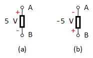
Figure 1.1: Two Equivalent Voltage Representations
For example, Fig. 1.1(a) and (b) are two versions of exactly the same voltage:
- In (a), terminal A has a potential that is +5 V higher than terminal B.
- In (b), terminal B's potential is -5 V higher than terminal A's (alternatively described as +5 V lower than terminal A).
The double-subscript notation, ${v_{ab}}$, is utilized to express the potential at point a relative to point b. Generally, this results in ${v_{ab}} = - {v_{ba}}$. Therefore, in Figure 1.1, ${V_{AB}} = 5\;V$ and ${V_{BA}} = - 5\;V$.
Example: If it takes 1 joule of work to move a charge of 1 coulomb from point A to point B, then the voltage between points A and B is 1 volt.
Current (I)
Current (I)
- Definition: Current is the rate at which electric charge flows past a point in a circuit. It is measured in amperes (A), where 1 ampere equals 1 coulomb per second (1 A = 1 C/s). Current can flow in two forms: direct current (DC), which flows in a constant direction, and alternating current (AC), which changes direction periodically.
- Mathematical Expression:
$i = {{dq} \over {dt}}$, $I = {Q \over t}$- Q: The charge is passing through a cross-section in time (t).
- Unit: The current unit is ampere (A).
- Direction of Current: Engineers use the convention of hole current to simplify equations. In reality, electrons flow from negative to positive, but we often consider the flow of positive charges (holes) for analysis.
Two indicators will specify the current flow along a lead or through an element:
- an arrow: establish a current reference direction
- a value (variable or fixed): quantify the current flow in the reference direction

Figure 1.2: Two Representations of the same current
Figure 1.2(a) shows a current of 3 A, equivalent to a charge flow of 3 coulombs per second (C/s), moving from left to right through the wire. Conversely, Figure 1.2(b) shows a current of -3 A flowing from right to left. Both scenarios facilitate the transfer of the same amount of charge and represent two equivalent methods of describing the same current flow.
Note: When current values are positive, this indicates that the direction of the current flow aligns with the reference current direction. Conversely, negative current values signify that the actual current flow direction is opposite to the reference direction.
Example: If a total charge of 3 coulombs passes through a wire in 3 seconds, the current in the wire is:
$i = {Q \over t} = {{3C} \over {3s}} = 1\quad A$
Power (P)
Power in Electrical Circuits
- Definition: Power refers to the rate at which energy is transferred or converted.
- Mathematical Expression: Power can be expressed as the derivative of energy to time:
$P = {W \over t} = V{Q \over t} = V \cdot I$- P: Power (watt, joule/second, or J/s)
- W: Energy
- t: seconds
- Unit: The standard unit of power is the watt (W).
Energy (W)
Energy (W) in Electrical Circuits
- Definition: Energy (W) in electrical circuits refers to the total amount of work done or heat delivered by the power over a period. The unit of energy in the International System of Units (SI) is the joule (J), where 1 joule is the energy transferred when 1 watt of power is applied for 1 second.
- Mathematical Expression: $W = P \cdot t$ (watt-seconds, W s, or joules)
- W: the energy in joules (J)
- P: the power in watts (W)
- t: the time in seconds (s) during which the power is applied
Voltage-Current Relationships and Energy Transfer
The voltage-current (V-I) relationships in electrical elements are fundamental to understanding how energy is either absorbed by or delivered to these elements within a circuit. Your summary points are crucial for deciphering the direction of power flow in circuit analysis. Here's a detailed explanation based on the provided items:
Understanding Polarity and Current Direction
To determine whether an element absorbs or delivers energy, we need to consider both the polarity of the voltage across the element and the direction of the current through it.
- The polarity of Voltage: The polarity across an element indicates the direction of the electric field within that element. The positive and negative terminals across the element determine it.
- Direction of Current: The direction in which positive charge carriers (conventionally regarded as the current direction) move through the element.
Absorbing Energy
An element absorbs energy when a positive current enters its positive terminal. This scenario implies that external forces (like a battery or another power source) are doing work on the charge carriers to push them through the element against the inherent electric field or potential difference. This work on the element increases its internal energy, manifesting as stored energy in capacitors or inductors or as dissipated energy in resistors.
Delivering Energy
Conversely, an element delivers energy to the circuit when a positive current leaves its positive terminal (equivalently enters its negative terminal). This indicates that the element had stored energy (in the case of capacitors or inductors) and is now releasing that energy back into the circuit. The element essentially acts as an energy source, driving the current through the circuit.
Examples (Referring to Fig 1.4):

Figure 1.4: Various Voltage-Current Relationships
- Absorbing Energy:
- (a): The element is absorbing energy. A positive current enters the positive terminal.
- (b): Similar to (a), it absorbs energy.
- Delivering Energy:
- (c): The element is delivering energy. A positive current leaves the positive terminal.
- (d): It delivers energy from the positive current entering the negative terminal.
Relationship Between Voltage, Current, and Resistance (Ohm's Law)
Relationship Between Voltage, Current, and Resistance (Ohm's Law)

Ohm's Law describes the relationship between voltage (V), current (I), and resistance (R) in a circuit. It states that the voltage across many types of conducting materials is directly proportional to the current flowing through the material. The formula expresses this relationship:
$V = I \cdot R\quad \Leftrightarrow \quad I = {V \over R}\quad \Leftrightarrow \quad R = {V \over I}$
where:
- V : is the voltage across the conductor (in volts, V)
- I : is the current through the conductor (in amperes, A)
- R : is the resistance of the conductor (in ohms, Ω).
Calculating Voltage
If a device has a resistance of 5 ohms and a current of 2 amperes is flowing through it, the voltage across the device can be calculated as:
$V = I \cdot R = 2\;A \times 5\;\Omega = 10\quad V$
These examples illustrate the foundational concepts of electric charges, electric fields, voltage, and current in circuit analysis. Understanding these principles is crucial for analyzing and designing electrical and electronic circuits.
Calculating Current
Given: A resistor with a resistance of 10 Ω is connected across a voltage source of 5 V.
Find: The current flowing through the resistor.
Solution:
Using Ohm's Law ($V = R \cdot I$), we can solve for I:
$I = {V \over R} = {{5\;V} \over {10\;\Omega }} = 0.5\quad A$
Conclusion: The current flowing through the resistor is 0.5 A.
Calculating Resistance
Given: A voltage of 12 V causes a current of 4 A to flow through a resistor.
Find: The resistance of the resistor.
Solution:
Rearrange Ohm's Law to solve for R: $R = {V \over I}$
$R = {V \over I} = {{12\;V} \over {4\;A}} = 3\quad \Omega $
Conclusion: The resistance of the resistor is 3 Ω.
It is important to note that Ohm's Law applies to conductors whose resistance remains constant over various voltages and temperatures. This law is foundational in circuit analysis, allowing for calculating voltage, current, or resistance in a circuit when two of these quantities are known, facilitating the design and analysis of electrical and electronic circuits.
1.2 System Units
In Engineering Circuit Analysis, as in all fields of engineering and physics, the International System of Units (SI) is the standard system of units used to measure physical quantities. Understanding these units is fundamental for analyzing and designing electrical circuits. Here's an overview of the key units relevant to circuit analysis:
Length:
- Unit: Meter (m)
- Description: The meter is the basic unit of length in the SI system. It is defined as the distance light travels in a vacuum in 1/299,792,458 of a second.
- Commonly used prefixes: millimeter (mm), centimeter (cm), kilometer (km).
Mass:
- Unit: Kilogram (kg)
- Description: The kilogram is the SI unit of mass. It is defined by the mass of a specific platinum-iridium alloy cylinder stored at the International Bureau of Weights and Measures in Sèvres, France.
- Commonly used prefixes: milligram (mg), gram (g)
Time:
- Unit: Second (s)
- Description: The second is the SI base unit of time. It is defined as the duration of 9,192,631,770 periods of radiation corresponding to the transition between two hyperfine levels of the ground state of the cesium-133 atom.
- Commonly used prefixes: millisecond (ms), microsecond (μs).
Electric Charge:
- Unit: Coulomb (C)
- Description: The coulomb is the SI unit of electric charge. One coulomb equals the amount of charge transferred by a current of one ampere in one second.
Force:
- Unit: Newton (N)
- Description: The Newton is the SI unit of force. It is defined as the force necessary to accelerate a mass of one kilogram at a rate of one meter per second squared (1 N = 1 kg·m/s²).
Unit of Work or Energy:
- Unit: Joule (J)
- Description: The joule is the SI unit of work or energy. One joule is the amount of work done when a force of one newton displaces an object by one meter in the direction of the force (1 J = 1 N·m).
Power:
- Unit: Watt (W)
- Description: The watt is the SI unit of power. One watt represents one joule per second (1 W = 1 J/s). It measures the rate of energy conversion or transfer.
Voltage:
- Unit: Volt (V)
- Description: The volt is the SI unit of electric potential difference (voltage). One volt is defined as the difference in electric potential that drives one ampere of current against one ohm of resistance (1 V = 1 W/A).
Current:
- Unit: Ampere or amp (A)
- Description: The ampere is the SI base unit of electric current.
- Earlier, the ampere was defined as the constant current that, if maintained in two straight parallel conductors of infinite length and negligible circular cross-section and placed one meter apart in a vacuum, would produce a force between these conductors of 2×10⁻⁷ newtons per meter of length.
- Named for 19th-century French physicist André-Marie Ampère, it represents a flow of one coulomb of electricity per second (1A = 1 C/s). A flow of one ampere is produced in a resistance of one ohm by a potential difference of one volt (1A = 1 V/Ω).
These fundamental units form the basis of electrical engineering concepts, including circuit analysis. They are essential for quantifying and understanding the physical phenomena at play within electrical systems.
1.3 Passive Elements
Passive elements are the fundamental building blocks of electrical circuits. Unlike active elements (e.g., transistors and operational amplifiers), they cannot independently amplify or generate electrical power. Instead, they control, store, or dissipate the energy provided by an external source (typically a voltage or current source). Here's a breakdown of the most common passive elements and their functionalities:
Resistors (R)
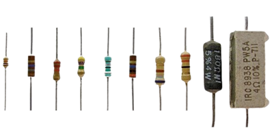
Resistors are perhaps the simplest passive components, primarily used to limit current, divide voltages, and dissipate power as heat. They oppose the flow of electrons through a material, a property known as resistance, measured in Ohms (Ω).
- Function: Resistors convert electrical energy into heat, reducing current flow according to Ohm's Law ($V = I \cdot R$), where V is the voltage across the resistor, I is the current flowing through it, and R is its resistance.
- Applications: When paired with capacitors, resistors are integral for setting circuit conditions such as current flow or voltage levels, filtering signals, and timing circuits in virtually every electronic circuit.
- Symbols:

Inductors (L)
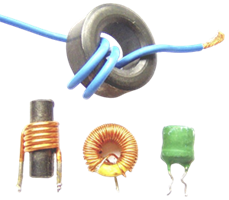
Inductors store energy in a magnetic field created by electrical current flowing through a coil of wire. Inductance, the measure of an inductor's ability to store magnetic energy, is measured in henries (H).
- Function: The fundamental property of inductors is that they oppose changes in current flow through them. This property is described by $v = L{{di} \over {dt}}$, where v is the voltage across the inductor, L is its inductance, and ${{di} \over {dt}}$ is the rate of change of current over time.
- Applications: Inductors are used in filtering, tuning, and frequency selection circuits, such as in radios and TVs, to select desired frequencies. They are also integral to transformers and power supply circuits.
- Symbol:

Capacitors (C)

Capacitors store energy in an electric field between two conductive plates separated by an insulating material (dielectric). They are characterized by capacitance, which is the ability to store an electrical charge, measured in farads (F).
- Function: When a voltage is applied across the plates, an electric field is established, storing energy that can be released when the circuit requires it. The relationship between the voltage (v) across a capacitor (C) and the charge (q) it holds is given by $q = C \cdot v$, where C is the capacitance.
- Applications: Capacitors are used in filtering applications to allow alternating current (AC) signals to pass while blocking direct current (DC) signals, in energy storage, in power supply smoothing, and in timing applications when combined with resistors.
- Symbol:

Passive vs. Active Elements:
The distinction between passive and active elements is crucial:
- Passive Elements: Do not require an external power source to operate and cannot amplify a signal. Their output power is always less than or equal to the input power. Resistors, capacitors, and inductors fall into this category.
- Active Elements: These can introduce power into a circuit and are capable of amplifying signals. Examples include transistors and operational amplifiers.
Key Characteristics of Passive Elements:
- Linear vs. Non-linear:
- Linear: Resistors exhibit a linear relationship between voltage and current (Ohm's Law applies).
- Non-linear: Some capacitors and inductors might exhibit non-linear behavior at high voltages or currents.
- Energy Transfer:
- They can dissipate energy (resistors), store and release energy (capacitors and inductors), or combine both.
- They cannot generate new energy.
Understanding the behavior and application of these passive elements is essential for circuit analysis and design, forming the foundation upon which more complex circuits and systems are built. Their properties determine how circuits respond to signals and power levels, influencing everything from signal processing to power management in electronic systems.
1.4 Power Sources
Ideal Voltage Source
Ideal Voltage Source:
An ideal voltage source maintains a fixed voltage difference between its two terminals regardless of the current drawn from it.
- Independent Voltage Source: Delivers a constant voltage that does not depend on any other circuit variable.
- Dependent Voltage Source: Its output voltage depends on another voltage or current in the circuit (often noted with a controlling variable, e.g., $\alpha {V_x}$
Independent Voltage Sources
Independent Voltage Sources
- Definition: Independent voltage sources provide a specific voltage that can be constant ${V_S}$ or time-varying ${v_S}(t)$. The voltage level is maintained across the source's terminals irrespective of the variations in circuit conditions or the current drawn by the circuit.
- Symbol and Identification: Independent voltage sources are typically represented by a circle with a plus (+) and minus (-) sign to indicate polarity, sometimes with a battery symbol for DC sources or a sine wave for AC sources.

Independent Current Sources
- Definition: These sources deliver a specified current constant $I$ or time-varying ${i_S}(t)$. The current is independent of the voltage across the source's terminals or any circuit load changes.
- Symbol and Identification: Represented by a circle with an arrow inside, pointing toward conventional current flow (positive to negative).

Dependent Current Sources
Dependent (or controlled) sources are critical elements in circuit analysis, especially in studying amplifiers, active filters, and integrated circuits. Unlike independent sources, whose values are fixed, dependent sources derive their output (voltage or current) based on another quantity in the circuit, such as a voltage or current elsewhere in the system. This relationship makes them essential for modeling the behavior of many electronic components, including transistors and operational amplifiers.
Types of Dependent Sources:
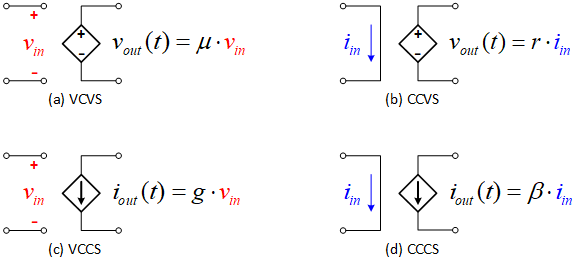
Figure 1.5: (a) VCVS; (b) CCVS; (c) VCCS; (d) CCCS
There are four primary types of dependent sources, categorized by their input (control) and output variables:
- Voltage-Controlled Voltage Source (VCVS):
- Output: Voltage
- Control Variable: Voltage
- Symbol & Notation: Often represented with a diamond shape. The output voltage is a function of a voltage elsewhere in the circuit, typically denoted as ${v_{out}}(t) = \mu \cdot {v_{in}}$, where $\mu $ is the voltage gain.
- Current-Controlled Voltage Source (CCVS):
- Output: Voltage
- Control Variable: Current
- Symbol & Notation: Similar to VCVS but indicates that the output voltage depends on an input current, expressed as ${v_{out}}(t) = r \cdot {i_{in}}$, where $r$ is a proportionality constant, often referred to as the transresistance.
- Voltage-Controlled Current Source (VCCS):
- Output: Current
- Control Variable: Voltage
- Symbol & Notation: Also typically represented with a diamond shape but includes notation or a symbol indicating current output. The relationship can be defined as ${i_{out}}(t) = g \cdot {v_{in}}$, where $g$ is the transconductance.
- Current-Controlled Current Source (CCCS):
- Output: Current
- Control Variable: Current
- Symbol & Notation: Similar in representation to the other sources but denotes a current output that depends on an input current, described as ${i_{out}}(t) = \beta \cdot {i_{in}}$, where $\beta $ is the current gain.
Real Voltage Source
Real Voltage Source
In circuit analysis, an ideal voltage source is assumed to provide a constant voltage regardless of the load. However, real voltage sources (e.g., batteries) exhibit non-ideal behavior because of internal losses and leakage paths. These are commonly modeled using:
- Series Internal Resistance (𝑅𝑠): Represents the resistive losses in the battery’s materials, connections, and electrolyte.
- Parallel Internal Resistance (𝑅𝑝): Models leakage currents (or self-discharge) within the battery, offering an alternate path for current even when no load is connected.
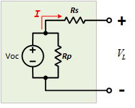
Equivalent Circuit of a Real Voltage Source (Battery)
- Voc: The ideal (open-circuit) voltage of the battery.
- 𝑅𝑠: The series resistor that accounts for internal resistive losses.
- 𝑅𝑝: The parallel resistor that accounts for leakage currents and self-discharge.
Series Internal Resistance (𝑅𝑠)
Series Internal Resistance (𝑅𝑠)
Physical Meaning and Origins
- Resistive Losses:
𝑅𝑠 captures the resistive effects due to the battery’s internal components, such as the electrodes, electrolyte, and contact interfaces. - Voltage Drop Under Load:
When current 𝐼 flows from the battery, a voltage drop of 𝐼⋅𝑅𝑠 occurs across 𝑅𝑠. This reduces the effective voltage available to the external circuit.
Model Representation
- Equivalent Circuit:
The ideal voltage source (with open-circuit voltage 𝑉𝑜𝑐) is placed in series with 𝑅𝑠. The voltage delivered to a load becomes:
${V_L} = {V_{OC}} - {I} \cdot {R_S}$ - Impact on Performance:
A higher 𝑅𝑠 leads to a more pronounced voltage drop under load, critical in high-current applications. In practice, 𝑅𝑠 can vary with the battery’s state of charge, temperature, and age.
Measurement and Practical Considerations
- Measurement Technique:
One common method to determine 𝑅𝑠 is to measure the open-circuit voltage, then apply a known load, measure the loaded voltage, and use the voltage drop and load current to compute 𝑅𝑠. - Design Implication:
Lower 𝑅𝑠 is desirable in applications that demand high currents, as it ensures minimal voltage loss.

$${R_S} = {{{V_{OC}} - {V_L}} \over {{I_L}}}$$
Parallel Internal Resistance (𝑅𝑝)
Parallel Internal Resistance (𝑅𝑝)
Physical Meaning and Origins
- Leakage and Self-Discharge:
𝑅𝑝 models the leakage paths inside the battery. Even in the absence of an external load, a small leakage current can flow through 𝑅𝑝, which leads to self-discharge over time. - High Resistance Characteristic:
In a well-maintained battery, 𝑅𝑝 is very high (often in the megaohm range), indicating minimal leakage.
Model Representation
- Equivalent Circuit:
𝑅𝑝 is connected in parallel with the ideal voltage source (and its series resistor 𝑅𝑠). This configuration allows you to capture both the ideal behavior and the leakage current:
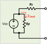
${I_{leak}} = {{{V_{OC}}} \over {{R_p}}}$
- Effect on Open-Circuit Behavior:
When no load is connected, almost all of the battery voltage appears at the output, with only a tiny current flowing through 𝑅𝑝. However, in precise analyses — especially for long-term storage — the presence of 𝑅𝑝 cannot be ignored.
Measurement and Practical Considerations
- Measurement Technique:
𝑅𝑝 is usually estimated from the battery’s self-discharge characteristics over time. A very high 𝑅𝑝 indicates low leakage, which benefits battery longevity. - Design Implication:
A high 𝑅𝑝 is advantageous in circuits where maintaining charge over time is critical, as it minimizes unwanted discharge.
1.5 Voltage Notations
In Engineering Circuit Analysis, understanding the notation used to describe voltage sources and their relationship to the ground and the double-subscript and single-subscript notations is essential for accurately analyzing and interpreting circuits. Let's dive into these notations to clarify their meanings and applications.
Voltage Sources and Ground
Voltage Sources and Ground
In electrical and electronic circuits, the ground is a common reference point for voltage measurements, ensuring safety and a reference for potential levels across the circuit. The ground is typically assigned a potential of zero volts. This concept is essential for several reasons:
- Reference Point: It establishes a zero-voltage reference point for measuring voltages in the circuit.
- Safety: It provides a path for fault currents to flow to the earth, potentially preventing damage to equipment and personnel.

Figure 1.6: Ground Potential
Grounding in Circuits:
Figure 1.7 shows different grounding methods for components like batteries and resistors. This ensures specific points in the circuit (like the negative terminal of a battery or the bottom of a resistor) are at zero voltage (ground potential). Grounding establishes a common reference point for voltage measurements. Even with different schematic symbols, the ground connection concept remains consistent for clarity and safety in circuit analysis.
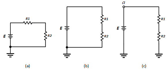
Figure 1.7: Three Ways to Sketch the Same Series DC Circuit
Fig. 1.8 shows that voltage source symbols can be replaced with conventional ones with a battery and a ground connection.

Figure 1.8: Replace the notation for DC supply with the Standard Ground Notation
Single-Subscript Notation
Single-Subscript Notation
Double-Subscript Notation
Double-Subscript Notation
Double-subscript notation denotes the voltage difference between two points in a circuit, indicating the direction of potential rise from one point to another.
Format: Vab signifies the voltage at point a relative to point b. If E = 12 V, and point a is mentioned as 12V positive to ground, this notation helps understand voltage drops or gains between specific points in a circuit.